Sign In
Upload
Manuals
Brands
General Dynamics Manuals
Control Systems
7200
General Dynamics 7200 Manuals
Manuals and User Guides for General Dynamics 7200. We have
1
General Dynamics 7200 manual available for free PDF download: Operation And Maintenance Manual
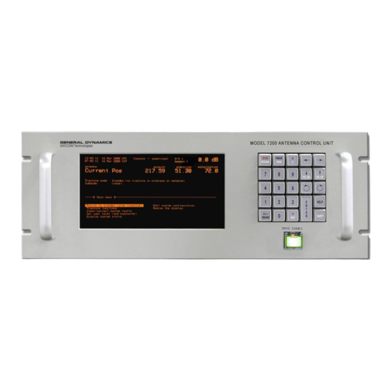
General Dynamics 7200 Operation And Maintenance Manual (253 pages)
ANTENNA CONTROL SYSTEM
Brand:
General Dynamics
| Category:
Control Systems
| Size: 4 MB
Table of Contents
Declaration of Conformity
4
Table of Contents
5
Scope
9
Organization of Included Contents
9
1 Introduction
9
Purpose
9
Supplemental Literature on CD and Website
10
Technical Support
11
Important Safety Information
11
Explanation of Safety Symbols
11
Technical & Environmental Specifications
11
User Supplied Power Cord Requirements
11
Note about Connecting/Disconnect from Mains Power
12
2 Overview of the 7200 Acs
15
General Information about the 7200 ACS
15
System Specifications
16
7200 Acs Specifications
16
System Configuration
17
Typical 7200 ACS Block Diagram
17
System Hardware
19
7200 ACU Hardware
20
7200 Antenna Control Unit Front Panel
20
7200 Antenna Control Unit Top View
22
7200 Antenna Control Unit Side View
22
Vertexrsi Central Processing Unit (VCPU) PCB Assembly
23
VCPU Card
23
Vcpu S2 Hex Rotary Switch Positions Definition
24
Vcpu S3 Hex Rotary Switch Positions Definition
25
Vcpu S6 Dip Switch Positions Definition
25
Vcpu S4 Dip Switch Positions Definition
25
Vcpu Performance Specifications
27
User Interface
27
Digital Input/Output Printed-Circuit Board Assembly
27
7200 Digital I/O Specifications
28
Resolver-To-Digital Converter Printed-Circuit Board Assembly
28
Optical Encoder Daughter Board (Optional - AZ and EL)
28
Dual Channel Resolver-To-Digital Converter PCB Assembly
29
IEEE-488 Interface (Optional)
29
Time and Frequency Processor Board (Optional)
29
ACU Chassis Assembly
29
Power Supply, EMI Filter and Fuse
30
7200 Power Input Specifications
30
Antenna Drive Cabinet Hardware
30
Drive Cabinet Block Diagram
31
Drive Cabinet Assembly
32
AZ and el Drive Inverters
33
Polarization Motor Control (POL and 4Th Axis)
33
Drive Cabinet Control Logic
33
Local Control
34
Drive Cabinet Overcurrent Protection
34
AZ and el Drive Motors
34
Absolute Position Transducers
34
Controls and Indicators
35
7200 ACU Controls and Indicators
35
Axis Overtravel Limit Switches
35
Drive Cabinet Low-Temperature Option
35
7200 Antenna Control Unit Display
36
The Alphanumeric Display
36
The Keypad
37
7200 Acu Keypad Controls
38
Drive Cabinet Controls and Indicators
39
Drive Cabinet Pmcu and Relay Pcb Controls
39
Drive Enable Switch
39
System Functions
40
Standby
40
Manual Control Via Portable Maintenance Control Unit (PMCU)
41
Manual Antenna Control from the Drive Cabinet
42
Manual Antenna Control from the Antenna Control Unit
42
Immediate Tracking
42
Move to Longitude
42
Move to Look Angles
42
Steptrack
43
Star Tracking
43
Intelsat 11-Element Track
43
Orbital Element Track (Optional)
44
Tracking Functions
45
Orbit Prediction Tracking
45
3 Theory
47
Opt
47
Orbit Prediction
47
Orbit Determination
48
Short-Term and Long-Term OPT Solutions
48
Orbit Scan Theory
49
Orbit Scan Operation
50
4 Installation and Initial Setup of System
51
Mechanical Installation
51
Antenna-Mounted Components
51
Installing the Drive Cabinet
51
Overview
51
Installing the 7200 ACU
52
Mounting the 7200 Acu
52
System Cabling
54
7200 Antenna Control System Cabling Diagram
54
Drive Cabinet Main Power Connection
55
Drive Cabinet Assembly
55
Connecting the Drive Motors to the Drive Cabinet
56
Motor Connections to the Drive Cabinet
56
Limit Switch Connections to the Drive Cabinet
57
Installing the 7200 ACU Control Cable
58
Standard System 7200 ACU Control Cable Installation
58
Rear Panel Connectors
58
7200 Antenna Control Unit Rear Panel
58
Standard System 7200 ACU EIA/TIA-422B Cable Installation
59
Control Cable Connections
59
PMCU Connections
60
PMCU Display Setup
61
Resolver and Encoder Connections
61
Resolver Connections
61
Optical Encoder Connections
63
17/19-Bit Optical Encoder Connections Table
65
26-Bit Optical Encoder Connections Table
65
18-Bit Optical Encoder Connections Table
65
Position Display Unit Table
66
Analog Input Connections
66
A/D Circuit Calibration
67
Digital Inputs
67
Remote Communications Connections
68
Communication Port Connections
69
Remote Beacon Select and Summary Fault Connections
70
Initial Power-Up and System Setup
71
Drive Cabinet Power-Up and Initialization
72
Initial Power-Up
72
Inverter Drive Setup (AZ/EL Drv Modules)
72
Inverter Drive Operation
72
GPD315 Digital Operator Indicator and Key Description
73
Digital Operator Led Function Descriptions
74
Digital Operator Indicator and Key Description
74
V1000 Inverter Drive Operation
75
V1000 Keys, Displays, and Leds
75
Menu Structure for Digital LED Operator
76
V1000 Digital LED Operator Screen Structure
76
Changing Parameter Settings or Values on V1000 Drives
77
Gpd315 Drive Parameters
78
Inverter Drive Setup (Function Parameters)
78
V1000 Drive Parameters
79
AZ Motor Phasing
80
Drive Motor Phasing
80
EL Motor Phasing
80
Electrical Limit Switch Tests and Preliminary Settings
81
POL Motor and 4Th Axis Motor Phasing
81
ACU Power-Up and Initialization
82
AZ and el Speed Adjustments
82
Setting Beacon Signal Level and Slope
83
Setting Position Parameters
83
5 Operation
85
The 7200 ACS Menu System
85
Introduction
85
Multiscreen Menus
86
7200 ACS Basic Menu System
86
Menu Items
87
The Help System
87
Tracking Functions Menu System
87
ACS Help Screen (Parameter Help Screen)
88
7200 ACS Help Screen (Introductory Help)
88
System Prompts
89
Error Messages for Incorrect Entries
89
Parameter Edit Screen
89
Confirmation Messages
90
Parameter and Data Storage
90
Power-Up Procedures
90
Manual Movement of the Antenna
91
Manual Movement from the Drive Cabinet (PMCU)
91
Manual Movement from the ACU
92
The 7200 ACS Main Menu
92
Return to Standby (Stop Tracking) Function
93
Tracking Functions Menu
93
Track a Target Screen
93
Track a Target Menu
94
Manually Bias Target Function
95
Manually Bias Target Screen
95
Modify Current Target Menu
95
Tracking Receiver Parameters
96
253 Parameters
97
Analog Tracking Parameters
97
Dtr Parameters
97
Trl Parameters
97
Edit Current Target Menu
98
Reset OPT Target Function
98
Set Star Time Bias Function
98
Immediate Tracking Menu
99
Steptrack Parameters
99
Edit Steptrack Parameters... Menu
101
7200 ACU Keypad Momentary and Sticky Modes
102
Manual Antenna Control Function
102
Manual Antenna Control Screen
102
Antenna Speed Selection Control from the ACU
103
Edit a New or Existing Target Menu
103
Creating a Target Name
104
Target Name Parameter
104
Editing a Target Name
105
Erasing a Target Name
105
Tracking Mode Parameter
106
Edit Target Parameters Menu
107
Star Tracking Mode Parameters
107
Star Tracking Parameters
107
OPT Tracking Mode Parameters
108
Spacecraft Parameters
108
Calibrate Tracking Signal
109
Opt Parameters
109
Advanced Opt Parameters
110
Non-Geosynchronous Support Parameters
111
Intelsat 11-Element Tracking Mode Parameters
112
Move to Longitude Tracking Mode Parameters
113
Move to Look Angles Tracking Mode Parameters
113
Orbital Element Tracking (OPTIONAL)
114
Orbital Element Tracking Parameters
114
Edit Schedule Menu
115
Start Target Scheduler
115
Target Scheduler Menu
115
Add a New Entry Menu
116
View/Edit Existing Entries Menu
116
Delete All Entries Function
117
Delete One Entry Menu
117
Clear/Correct System Faults Function
118
Clear/Correct System Faults
119
7200 ACS Passwords
120
7200 ACS User Levels
120
Set User Level (and Passwords) Menu
120
Display System Status Menu
121
A/D States
122
Hardware Diagnostics
122
Input States
122
Output States
122
VCPU Hardware Diagnostics
123
RDC States Display
123
ACE DUART Diagnostics
124
Finite State Machine States
125
Position Loop Diagnostics
125
Steptrack Statistics
125
OPT Statistics
126
Box Limits
127
Orbit Data
127
Orbit Data Calculations
127
Background Tasks
128
Simulated Target
129
Star Viewing Windows
129
View Message Buffer
130
Serial Diagnostics Menus
131
Serial Dtr Diagnostic Fields
131
Serial DTR Diagnostics
131
Power-Up Test Report
132
Serial 253 Diagnostics
132
Serial TRL Diagnostics
132
ACU-CONFIG Firmware Options
133
Firmware Version Information
133
Network Diagnostics
134
Edit System Configuration Menu
136
Tracking Receiver Parameters Menu
136
Calibrating the Tracking Signal
137
Receiver Controller Parameter
137
Tracking Receiver Setup Menu
137
Position Encoder Configuration Menu
138
Position Encoder Configuration Parameters
138
Steptrack Defaults Menu
138
Supported Encoder Types
139
Motion Limits Menu
140
Motion Limits Parameters
141
Soft Limits
142
Motion Errors
143
Immobile and Reversed Errors
143
Runaway Errors
144
Position Loop Parameters
145
Built-In Simulator Setup
146
Antenna Simulator Setup
146
Spacecraft Simulator Setup
147
Antenna Simulator Parameters
147
Spacecraft Simulator Parameters
147
Set UTC Date and Time
148
Site Data
149
Site Data Parameters
150
Rf/Geometry
151
Rf/Geometry Parameters
151
Network Configuration
153
Test Configuration Parameter
153
IP Address
153
Bit Hex Binary Description
153
Subnet Mask
154
Gateway Address
155
TCP Port
156
Shell
156
Echo
156
Newline
156
Checksums
157
Screen Lines
157
Remote Port Configuration
157
Logical Port to Physical Port Conversion Table
158
Remote Port Configuration Parameters
159
ACU Sync Configuration (OPTIONAL)
160
User Interface Options Menu
161
User Interface Options Settings
161
Tracking Restoration Options Menu
163
Tracking Restoration Options Parameters
163
Factory Tests
164
Video Tests
164
Keyboard Test
165
Reset ACU to ROM Defaults
166
I/O Loopback Tests
166
Force Faults Clear
166
Clear Message Buffer
166
Message Printer Options Parameters
167
6 Maintenance
169
Air Filter
169
7200 ACU Rear Panel Fan
169
Checking the Battery
170
Replacing the Battery
170
Power Entry Module Fuse
170
7 Engineering Drawings
171
APPENDIX A Acronyms and Abbreviations
173
APPENDIX B 7200 ACU Password Protection
177
Setting Excitation Voltage
181
APPENDIX C Two Speed Resolver Calibration
181
Two-Speed Internal Alignment
182
Tracking Tutorial
183
Fault/Error Topics
191
APPENDIX D Tracking Tutorial for Operators
191
APPENDIX E 7200 Troubleshooting Guide
191
Drive Cabinet Unresponsive/Inverter Display Blank
192
Drive Cabinet Inverter Faults
192
Overcurrent [Oc]
193
Overvoltage [Ov]
193
Undervoltage [Uv]
193
Overheating [Oh]
193
7200 ACU Power-Up Failures
194
No Audible Beep at Power-Up
194
Display Shows Blinking Cursor Only
194
CPU Boot-Up Failure
194
Bus Error Occurs on Boot up
195
Soft and Hard Travel Limits
195
Axis Immobile with Summary Limit (Hard Limit)
195
Summary Limit Fault (When Antenna Is Not in a Limit)
195
Resolver Errors
196
Resolver Readout Bobble
196
Resolver Readouts Erratic with Antenna Motion
197
Resolver Readouts Not Changing with Antenna Motion
197
7200 ACU Error Messages
198
Axis Fault (Applies To: AZ, EL)
198
Box Violation Limit (Applies To: Four Compass Directions)
198
Brake Set (Applies To: AZ, el - Systems with Brakes Only)
198
Bus Error “Card Name and Number” (Applies To: All Systems)
199
Encoder Error (Applies To: AZ or EL)
199
Immobile (Applies To: AZ, EL, and POL)
199
Intelsat Data Expired
199
Intelsat Pre-Epoch Prediction
200
Invalid Target in Target Schedule
200
Keyboard Stop
200
Non-Volatile RAM Corrupted
200
OPT Cannot Track (Applies To: All Systems)
201
Remote Control Panel Link Failure
201
Reversed (Applies To: AZ, el and POL)
201
Simulation (Applies To: All Systems)
201
Soft Limit (Applies To: AZ, el or POL)
202
Summary Limit (Applies To: AZ, el or POL)
202
Sun Outage -- Steptrack Inhibited (Applies To: All Systems)
202
SYSFAIL Line - Timeout (Applies To: All Systems)
202
Tracking Receiver Fault
203
Tracking Receiver in LOCAL Control
203
Tracking Receiver out of Band
203
Tracking Receiver Serial Link Failure
203
Axis Immobile
204
Tracking Signal Input Saturated (Applies To: All Systems)
204
Axis Reversed
205
Axis Runaway
205
Position Loop Errors
205
Overshooting (Motor Turning on and off Repeatedly)
205
Too Long to Reposition to a New Satellite
206
Target Acquisition Errors
206
AST/OPT Tracking Errors
206
Target Tracking from Spacecraft
206
"Excessive Tracking Signal Noise" Error Displayed
207
Large Signal Fluctuation During AST Operations
207
Poor Tracking Performance
207
If the System Is Not Adequately Tracking
207
Intelsat (IESS-412) Tracking Errors
208
"Intelsat Data Expired" Error Displayed
208
"Intelsat Pre-Epoch Prediction" Error Displayed
208
"Intelsat Data Invalid--Cannot Track" Error Displayed
208
Site Test Procedure
209
Preliminary Information
211
Drive Cabinet Line Voltage Measurements and Power-Up
211
3-Phase Systems
211
APPENDIX F Site Acceptance Test Procedure
211
Motor Phasing Tests
212
Miscellaneous Error and Fault Messages
213
Limit Switch Tests
214
Three Axis System (if Applicable)
215
Four Axis System (if Applicable)
215
Manual Antenna Control Tests
216
Three Axis System
216
Four Axis System
216
Software Limit Tests
218
Motion Limits
218
Steptrack Tests
220
Input Signal Variation
220
Tracking Accuracy
221
Orbit Prediction Tracking (OPT)
222
System Parameter Recording
223
APPENDIX G Graphical Menu Tree
231
Main Menu
233
Mode Specific Parameters
234
Display System Status
235
Edit System Configuration
236
APPENDIX H Vendor Data
237
Field Procedure to Install CTB055
239
Standard Method
239
Alternate Method if Ctb055 Is Not Available
239
APPENDIX J Field Procedure to Install CTB055
241
NORAD Tracking
241
Element Set Format
241
CP/LP PATH Option Notes
247
Changes to User Interface
247
Status Examples
247
Target Editing Changes
248
M&C Support
249
Additional Support for CP_LP-PATH
250
Diagnostics
251
Advertisement
Advertisement
Related Products
General Dynamics Categories
Antenna
Measuring Instruments
Laptop
Receiver
Control Systems
More General Dynamics Manuals
Login
Sign In
OR
Sign in with Facebook
Sign in with Google
Upload manual
Upload from disk
Upload from URL