Sign In
Upload
Manuals
Brands
GE Manuals
Control Unit
IC3645SP7U350N9
GE IC3645SP7U350N9 Manuals
Manuals and User Guides for GE IC3645SP7U350N9. We have
1
GE IC3645SP7U350N9 manual available for free PDF download: Installation And Operation Manual
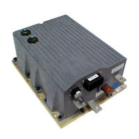
GE IC3645SP7U350N9 Installation And Operation Manual (69 pages)
SEPARATELY EXCITED (SX) TRANSISTORIZED TRACTION MOTOR CONTROL AND SERIES PUMP MOTOR CONTROL
Brand:
GE
| Category:
Control Unit
| Size: 1.03 MB
Table of Contents
Table of Contents
2
Auxiliary Speed Control
6
Field Weakening
6
Accelerator Volts Hold off
7
Anti-Rollback
7
On-Board Coil Drivers and Internal Coil Suppression
7
Pulse Monitor Trip (PMT)
7
Ramp Operation
7
Ramp Start
7
Speed Limits
7
Static Return to off (SRO)
7
Steer Pump Contactor Time Delay
7
System Protective Override
7
Battery Discharge Indication (BDI)
8
Diagnostics
8
Hourmeter Readings
8
Internal Resistance Compensation
8
Low Voltage
8
Maintenance Alert and Speed Limit
8
Standard Codes
8
Status Codes
8
Stored Codes
8
Systems Diagnostics
8
Circuit Board Coil Driver Modules
9
Dash Display Interaction Modes
9
Hydraulic Pump Control
9
Truck Management Module (TMM)
9
Ordering Information, Elementary and Outline Drawings
10
Ordering Information for Separately Excited Controls
10
Outline: SX-4 and SR-4 Package Size
11
Outline: SX-3 and SR-3 Package Size
12
Traction Elementary
13
Pump Elementary
14
Traction and Pump Control Input / Output List
15
Troubleshooting and Diagnostic Status Codes
16
General Maintenance Instructions
16
Cable Routing and Separation
16
Application Responsibility
16
Signal/Power Level Definitions
16
Low Level Signals (Level L)
16
High Level Signals (Level H)
17
Medium-Power Signals (Level MP)
17
High-Power Signals (Level HP)
17
4.2.3. Cable Spacing Guidelines
17
4.2.3.A General Cable Spacing
17
4.2.4 Cabling for Vehicle Retrofits
17
4.2.5 RF Interference
17
Suppression
17
Recommended Lubrication of Pins and Sockets Prior to Installation
18
Controller Mounting Guidelines
19
Necessary Tools
19
The GE Control Mounting Surface
19
Vehicle Mounting Surface
19
Application of Thermal Compound
19
Mounting the GE Control
20
Maintenance
20
General Troubleshooting Instructions
20
Traction Controller Status Codes
22
TMM Module Status Codes
39
Pump Control Status Codes
44
Truck Management Module (Tmm)
51
General Features
51
Operation
51
Installation
51
Connection Diagrams
51
TMM7A Card Connections
51
TMM7A Typical Brush Wear Sensor Connections
51
TMM Pump Control Connections
52
Typical Brush Wear Sensor Connections for Pump Control
52
TMM7A Outline Drawings
52
Sx Family - Ge Handset Instructions
53
General Features
53
Purpose/Setup Functions
53
Setup Function Procedures
54
Setup Mode
54
Status Code Scrolling
54
SX Handset Plug Connections & Outline Drawing
54
Setup Functions for Traction Controller
55
Summary of Current Limit Adjustments
61
Setup Functions for Hydraulic Pump Controller
62
Dash Displays
65
Application
65
Standard Dash Displays
65
Interactive Custom Dash Displays
65
Start-Up Display Sequence
66
Outline Drawings
66
Memory Map
67
Traction Control
67
Advertisement
Advertisement
Related Products
GE SX TRANSISTOR CONTROL IC3645SP4U400N3
GE IC3645SP4U450N10
GE IC3645SR4T405CT1
GE IC3645SR4W606N6
GE IC3645SR7W455N8
GE IC3645SR7T405T5
GE IC3645SR4W10010HL1
GE IC3645SR7W10010HL1
GE IC3645SP4U450Z1
GE IC3645SP4R400U2
GE Categories
Refrigerator
Ranges
Microwave Oven
Air Conditioner
Dishwasher
More GE Manuals
Login
Sign In
OR
Sign in with Facebook
Sign in with Google
Upload manual
Upload from disk
Upload from URL