Sign In
Upload
Manuals
Brands
GE Digital Energy Manuals
Measuring Instruments
Kelman MINITRANS
GE Digital Energy Kelman MINITRANS Manuals
Manuals and User Guides for GE Digital Energy Kelman MINITRANS. We have
1
GE Digital Energy Kelman MINITRANS manual available for free PDF download: Installation Manual
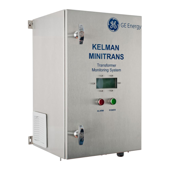
GE Digital Energy Kelman MINITRANS Installation Manual (84 pages)
Transformer Oil Dissolved Gas and Moisture Monitor
Brand:
GE Digital Energy
| Category:
Measuring Instruments
| Size: 4 MB
Table of Contents
Table of Contents
2
Introduction
6
Product Overview
6
Manual Scope
6
Safety
7
Symbols
7
Warnings
7
Requirements
9
Pre-Installation
9
Handling & Storage
9
Technical Specification
10
Table 4-1: Technical Specification
10
Design Criteria
11
Table 5-1: Type Tests
11
Transformer Criteria
12
Mounting
13
Mounting Stand Installation
14
Mounting the Product to the Stand
15
Figure 7-1: the Product Mounted on a Stand
15
Direct Mount Cradle
16
Locking Mechanism
16
Figure 7-2: Direct Mount Cradle
16
Sun Canopy
17
Figure 7-3: Cradle-Mount Sun Canopy
17
Plumbing
18
Figure 8-1: Schematic Representation of an Installation
18
Figure 8-2: Examples of Possible Line Configurations (Three of Many)
18
Transformer Valves
19
Fill Valve
19
Drain Valve
19
Ancillary Valves
19
Figure 8-3: Possible Valve Locations of a Transformer
19
Cooling Loop Valves
20
Supply & Return Valves
20
Oil Supply
20
Oil Return
21
Tubing
21
Fitting Requirements
23
Figure 8-4: Product Connections - Bottom View
23
Fitting Instructions
24
Connection to Oil Supply Valve
24
Figure 8-5: Fitting Body and Tubing
24
Figure 8-6: Nut at 6 O'clock Position
24
Figure 8-7: Nut at 9 O'clock Position
24
Connection to Oil Return Valve
25
Figure 8-8: Bleed Assembly on Flange-Type Oil Return Valve
25
Figure 8-9: Flange Example
26
Figure 8-10: Return Assembly Kit
26
Figure 8-11: Bleed Assembly on Threaded-Type Oil Return Valve
27
Power
28
Connections
28
Figure 9-1: Bottom Plate Connections
29
Figure 9-2: Mains Fuse Holders with Fuses (Front - Inside)
29
Figure 9-3: Mains Fuse Holders with Terminal Connections (Top - Outside)
29
Battery
30
Figure 9-4: Earth Terminal on Bottom of Enclosure
30
Figure 9-5: Coin Cell Battery
30
Electronics
32
Input Board
32
Alarm Connections
32
Accessory Power
33
External Sensors
33
Figure 10-1: Accessory Power Points for 12 V and 24 V
33
Communications
34
Table 11-1: Product Communications Channels
34
Appendix A Installation Tools and Supplies
35
Appendix B Customer Checklist
36
Appendix C Installation Record
37
Appendix D Tubing Specification and Ordering Details
41
Appendix E Product Dimensions
44
Figure E-1: Front and Side Dimensions
44
Figure E-2: Base Dimensions
44
Appendix F Mounting Stand Dimensions
45
Figure F-1: Front and Side Dimensions with Stand
45
Appendix G Footprint Dimensions
46
Figure G-1: Footprint Dimensions
46
Appendix H Sun Canopy Dimensions
47
Figure H-1: Mounting-Stand Canopy Front Dimensions
47
Figure H-2: Mounting-Stand Canopy Side Dimensions
47
Figure H-3: Cradle-Mount Canopy Front Dimensions
48
Figure H-4: Cradle-Mount Canopy Side Dimensions
48
Appendix I Input Board
49
Figure I-1: Input Board
49
Table I-1: List of Terminals
50
Figure I-2: RS-232 & RS-485 Connections
51
Appendix J Heat Trace Cable
52
Appendix K Direct Mount Cradle Vibration Levels
53
Figure K-1: Product Vibration Limits
54
Appendix L Direct Mount Cradle Installation
55
Figure L-1: Direct Mount Cradle
55
Figure L-2: Clearance Requirements
56
Table L-1: MINI DM-Cradle Retrofit Kit - KITT00071
57
Figure L-3: Foam Skid
58
Figure L-4: Product Positioned on the Foam Skid
58
Figure L-5: Bracket Tools and Fittings
59
Figure L-6: Attach Bracket Fittings to the Product
59
Table L-2: Bracket Tools and Fittings
59
Figure L-7: Tighten the Fittings
60
Figure L-8: Top Isolators Tools and Fittings
60
Table L-3: Top Isolators Tools and Fittings
60
Figure L-9: Fitting the Support Bracket
61
Figure L-10: Support Bracket with Top Isolators Fitted
61
Figure L-11: Mounting Slot Dimensions
61
Figure L-12: Bottom Isolators Tools and Fittings
62
Figure L-13: the Product Positioned over the Isolators
62
Table L-4: Bottom Isolators Tools and Fittings
62
Figure L-14: Isolator with O Ring
63
Figure L-15: Attach Fittings to Isolators
64
Figure L-16: Failsafe Tools and Fittings
64
Table L-5: Failsafe Tools and Fittings
64
Figure L-17: Fitting the Failsafe Mechanism
65
Figure L-18: Misalignment and Skew Distance
66
Figure L-19: Isolators Used in Compression and Compression Distance
66
Appendix M Direct Mount Cradle Locking Mechanism
67
Figure M-1: Isolator
68
Figure M-2: Misalignment and Skew Distance
68
Figure M-3: Isolators Used in Compression and Compression Distance
69
Figure M-4: Product LCD and Power Switch
70
Figure M-5: Tools & Fittings
71
Figure M-6: Top Isolators with Fittings & Failsafe Items Removed
71
Figure M-12: Tools & Fittings
71
Table M-1: Tools & Fittings
71
Figure M-7: Locking Piece Top
72
Figure M-8: Locking Piece with Fittings (Left) ¦¦ Tightened with a Nut Spinner (Right)
72
Figure M-9: Bottom Isolators with Partially Unscrewed Fittings
73
Figure M-10: Isolator with Fittings (Left) ¦¦ Tightened with Spanner (Right)
73
Figure M-11: Clockwise: Isolators with Fittings ¦¦ Back Fittings Tightened with Spanner ¦¦ Front Fittings Tightened with Nut Spinner
74
Figure M-13: Inner Panel
75
Figure M-14: Rear View of LCD Display Board with Cable Attached
75
Table M-2: Tools & Fittings
75
Figure M-15: Fitting PGA Locks
76
Figure M-16: Reconnect LCD Display Board Cable
77
Figure M-17: Inner Panel
77
Figure M-18: Loosen Isolator Front Nut with Nut Spinner
78
Figure M-19: Loosen Isolator Rear Outer Nut with Spanner
78
Figure M-20: Bottom Isolator with Fittings Removed
78
Figure M-21: Unscrew the Failsafe Bolt
79
Figure M-22: Loosen the Isolator M6 Nut Using a Nut Spinner
79
Figure M-23: Inverted Top Locking Piece
80
Figure M-24: Bottom Locking Piece
80
Figure M-25: Surplus Nuts & Washers Stored Securely on Bracket Bolts
80
Figure M-26: Inner Panel
81
Figure M-27: Rear View of LCD Display Board with Cable Attached
82
Figure M-28: Slide out PGA Lock
82
Figure M-29: Threaded Inserts
83
Figure M-30: Stored PGA Locks
83
Figure M-31: PGA Locks Secured Using Allen Key
83
Figure M-32: Reconnect LCD Board Cable
84
Figure M-33: Inner Panel
84
Advertisement
Advertisement
Related Products
GE Digital Energy Categories
Power distribution unit
Relays
Transceiver
Measuring Instruments
Control Unit
More GE Digital Energy Manuals
Login
Sign In
OR
Sign in with Facebook
Sign in with Google
Upload manual
Upload from disk
Upload from URL