Sign In
Upload
Manuals
Brands
GE Manuals
Power Supply
CPS3200U
GE CPS3200U Manuals
Manuals and User Guides for GE CPS3200U. We have
1
GE CPS3200U manual available for free PDF download: Product Manual
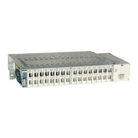
GE CPS3200U Product Manual (51 pages)
Upstream System, Remote Power System 48 Vdc Input, ±190 Vdc Output Converter/Limiter System
Brand:
GE
| Category:
Power Supply
| Size: 3 MB
Table of Contents
Table of Contents
2
Table of Figures
3
Table of Tables
4
Introduction
5
Reference Documents
5
Customer Service Contacts
6
On-Line Power Systems Product Manuals and Software
6
Product Description
7
Operation
7
Configurations
7
Figure 1 Block Diagram -48V Fed CPS3200U Shelf
7
Specifications
8
Table 1 Specifications
8
Ordering
9
Ordering Codes
9
Lugs
9
Table 2 Ordering Codes
9
Safety
10
Safety Statements
10
Figure 2 Capacitance Safety Limits
12
Warning Statements and Safety Symbols
13
Precautions
14
Pre-Installation
15
Purpose
15
Audience
15
Precautions
15
Safety
15
Installation Tools
15
System Identification
15
Installing the Shelf Level Upstream Product
16
Unpacking Shelf Level Upstream Product
16
Installing and Powering the CP3200U Converter Shelf
16
Figure 3 QS912A Converter Shelf
16
Figure 4 Mounting the Converter Shelf
16
Figure 5 Preparing to Make DC Connections to Converter Shelf
17
Figure 6 Making DC Connections to Converter Shelf
17
Ground the Shelf
18
Attach the Load Wiring
18
Figure 7 Grounding Converter Shelf
18
Figure 8 Output Wiring for Converter Shelves
19
Table 3 Output Connector Pinout
19
Set Shelf ID and Attach Alarm Wiring
20
Figure 9 Accessing Alarm Cards
20
Figure 10 Removing Alarm Card
20
Figure 11 Setting Shelf ID
21
Figure 12 Signal Wiring between Converter Shelves
21
Installing the Baffle
22
Installing the Fan Shelf
22
Figure 13 Installing a Baffle
22
Figure 14 Mounting the Fan Shelf
22
Figure 15 Inserting Fan Trays
23
Figure 16 Open the Wiring Region of the Fan Shelf
23
Figure 17 Alarm Wiring for Fan Shelf
24
Figure 18 DC Cabling Fan Trays in CPS3200U Systems
24
Figure 19 Cover the Wiring Region of the Fan Shelf
25
Figure 20 Fan Tray Leds
25
Installing the Filter Bracket and Filter
26
Figure 21 Mounting the Filter Bracket
26
Figure 22 Filter Retention Bracket
26
Figure 23 Install Filter
27
Figure 24 Secure Filter Retention Bracket
27
Inspect the Network - Check and Mark Wiring Compliance
28
Final Installation
29
Installing the Converters
29
Figure 25 Shelf Level ESD Jack
29
Figure 26 Installing Converters
29
Apply DC Power
30
Recognizing Normal States
30
Figure 27 QS982A Faceplate and Leds
30
QS982A LED Information Map
31
Table 4 QS982A LED Information Map
31
Confirm Operation of Alarm Wiring
32
Installing the QS941A Ethernet Module
32
Figure 28 Fan Shelf Right Hand Cover
32
Figure 29 Fan Shelf Controller Jumper
32
Figure 30 Preparing a Fan Shelf for a CPS Controller
33
Figure 31 Installing the Controller
33
Figure 32 Controller Wiring
34
Figure 33 Fan Shelf RS-485 Jacks
35
Figure 34 Signal Cables - System
35
Installing the Office Alarm Connector
36
Figure 35 Office Alarm Cable Pinout
36
Reference Information
37
QS982A Converter LED Information Map
37
Figure 36 QS982 Leds and Test Points
37
Table 5 QS982A Converter LED Information Map
37
QS982A LED Information Map (Visual)
38
Table 6 QS982A Converter LED Information Map (Visual)
38
Alarm Card Information
39
Figure 37 Alarm Card Faceplate
39
Figure 38 Shelf ID Rotary Switches
39
QS912A Converter Shelf
40
Figure 39 QS912A Dimensions
40
Figure 40 Output Connectors
41
Table 7 Output Connector Pinout
41
QS930A Fan Shelf
42
Figure 41 QS930 Fan Shelf Dimensions
42
Figure 42 QS930 Fan Shelf Connections and Fuses
42
10 Maintenance
43
Filter Cleaning
43
11 Product Warranty
44
Appendix A: Operating Temperature Measurement and Vertical Spacing
46
Operating Temperature
46
Baffles and Fan Trays
46
Figure 43 Converter Shelf with Slot Fillers
46
Appendix B: Alarm Reference Table
47
Table 8 Alarm Reference
47
Appendix C: Operation Without a Controller - Alarm Wiring
49
Figure 44 Alarm Card Office Alarm Pinout and Shelf ID
49
Figure 45 Alarm Card Office Alarm Cables
49
CPS3200U Shelf Alarm Card State Table
50
Alarm Card Logical Operation of Leds and Alarm Relays
50
Table 9 Shelf Alarm Card State
50
Revision History
51
Advertisement
Advertisement
Related Products
GE CS300 User's guide
GE CP39
GE CP52
GE CP61
GE CP9530D
GE CP9536*J series
GE CPCI3UX606
GE CP40S AYV Series
GE CP50S AYV Series
GE Cync CPLGOD2BLG1
GE Categories
Refrigerator
Ranges
Microwave Oven
Dishwasher
Air Conditioner
More GE Manuals
Login
Sign In
OR
Sign in with Facebook
Sign in with Google
Upload manual
Upload from disk
Upload from URL