Sign In
Upload
Manuals
Brands
Garmin Manuals
Control Systems
GFC 600H
Garmin GFC 600H Manuals
Manuals and User Guides for Garmin GFC 600H. We have
4
Garmin GFC 600H manuals available for free PDF download: Maintenance Manual, Pilot's Manual
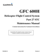
Garmin GFC 600H Maintenance Manual (158 pages)
Helicopter Flight Control System
Brand:
Garmin
| Category:
Control Systems
| Size: 8 MB
Table of Contents
Table of Contents
8
Revision and Distribution
14
Purpose
14
Applicability
14
Scope
14
Terminology
15
Reference Documents
17
Table 1-1 Reference Documents
17
2 System Description
18
GFC 600H Flight Control System Functions
19
Attitude Hold (ATT)
20
System Overview
20
Helicopter Electronic Stability and Protection (H-ESP)
21
Flight Director Modes
22
Figure 2-1 System Function Diagram
23
Figure 2-2 GMC 605H Mode Controller
24
GMC 605H AFCS Mode Controller
24
Figure 2-3 GMC 605H System Interface Overview
25
GFS 83 Force Trim Servo
26
Figure 2-4 GFS 83 Servo (-11 Variant)
27
Figure 2-5 GFS 83 Servo (-00 Variant)
27
Sensors
28
Table 2-1 Servo Program Pins and Configuration
28
Figure 2-6 GSU 75H, GMU 44, GMU 44B, and GTP 59 Sensors
29
Figure 2-8 GTP 59 OAT Probe
30
Figure 2-9 GMU 44 and GMU 44B Magnetometers
31
Figure 2-10 Collective Position Sensor
32
Power Requirements
33
Table 2-2 GFC 600H Electrical Loads
33
3 Control and Operation
34
GMC 605H Mode Controller
35
GMC 605H Normal Mode
35
Table 3-1 GMC 605H Normal Mode Key Descriptions
35
Figure 3-1 GMC 605H Normal Mode Operation
36
Table 3-2 Description of GMC 605H Normal Mode Operation
36
Figure 3-2 FCS Switches
37
Table 3-3 GFC 600H Switch Function
37
Figure 3-3 Yaw Switch
38
Figure 3-4 G500H Alerts and Annunciations Layout
39
Garmin Displays (G500H Installations)
39
Table 3-4 Description of GDU FCS Annunciation Bar
39
Figure 3-5 GMC 605H Configuration Mode Navigation
43
GMC 605H Configuration Mode
43
Figure 3-6 GMC 605H Configuration Mode Layout
44
Table 3-5 GMC 605H Configuration Mode Navigation
44
Table 3-6 GMC 605H Configuration Mode Layout
44
Figure 3-7 GMC 605H Configuration Mode Map
45
Software Loading
46
Figure 3-8 GDU Configuration Mode Home Screen
47
Figure 3-9 System Management Page
48
4 Instructions for Continued Airworthiness
50
On Condition Servicing
52
Periodic Maintenance
52
Required Tools
52
Servicing Information
52
Specialty Tools
53
Maintenance Intervals
54
Table 4-1 Periodic Maintenance Intervals
54
Lightning Strike
55
Visual Inspection
55
Electrical Bonding Check
57
Figure 2-7 GRS 79H
57
Magnetic Field Updates
57
Table 4-2 Existing Electrical Bonding Requirement (Milliohm)
57
Table 4-3 Repaired Electrical Bonding Requirement (Milliohm)
57
Servo Arm Torque Check
58
Figure 4-1 Armature Installation (P/N 011-03367-11)
59
Figure 4-2 Shear Fuse Installation
61
5 Troubleshooting
62
General Troubleshooting
63
Table 5-1 General Troubleshooting Guide
63
Crew Alerting System (CAS) Message Troubleshoot
65
GMC 605H Mode Controller
65
LED Indicator Diagnosis Information
65
Table 5-2 GMC 605H LED Indicators
65
Table 5-3 GMC 605H cas Troubleshooting
65
Configuration Mode Test Faults
68
Table 5-4 GMC 605H Configuration Mode (Post-Install Procedures) Test Faults
68
GRS 79H or GSU 75H ADAHRS and GMU 44( ) Magnetometer
71
Table 5-5 General Troubleshoot Guide for AHRS/ADC Install Tool
71
Table 5-6 ADC Field Calibration Troubleshooting
71
Table 5-7 Post-Install Procedures Troubleshooting
72
Table 5-8 Upload and Download Troubleshooting
74
Connectors
75
Figure 5-1 Rear View of GMC 605H Backplate
75
Figure 5-2 GMC 605H P6051/P6052 Connectors
75
Gmc 605H
75
Table 5-9 P6051 Connector Pinout
76
Table 5-10 P6052 Connector Pinout
77
Figure 5-3 GFS 83 P831-P/R/Y Connector
78
Gfs 83
78
Table 5-11 P831 Connector Pinout
78
Figure 5-4 GSU 75H J751 Connector
79
Table 5-12 J751 Connector Pinout
80
Figure 5-5 GSU 79H J791 Connector
81
Gsu 79H
81
Table 5-13 J791 Connector Pinout
82
Figure 5-6 GMU 44 J441 Pigtail Connector
83
Gmu 44
83
Table 5-14 J441 Connector Pinout
83
Figure 5-7 GMU 44B Connector
84
Gmu 44B
84
Table 5-15 J442 Connector Pinout
84
Collective Position Sensor
85
Figure 5-8 Collective Position Sensor P6053 Connector
85
Table 5-16 P6053 Connector Pinout
85
6 Equipment Removal and Re-Installation
86
Figure 6-1 Location of GFC 600H System Components
87
Figure 6-2 GMC 605H Installation
88
GMC 605H Mode Controller
88
GFS 83 Servo
90
Table 6-1 Bom for Pitch and Roll Servo Installation
90
Figure 6-3 GFS 83 Pitch and Roll Servo Installation
91
Table 6-2 Bom for Yaw Servo Installation
92
Figure 6-4 GFS 83 Yaw Servo Installation
93
Servo Control Push-Rod Linkage
94
Figure 6-5 Pitch Control Push-Rod Adjustment
96
Figure 6-6 Roll Control Push-Rod Adjustment
97
Figure 6-7 Yaw Control Push-Rod Adjustment
98
Servo
99
Shear Fuse
100
Figure 6-8 Pitch and Roll Clutchless Servo Output Arm and Shear Fuse Installation
101
Output Arm
101
Figure 6-9 Yaw Clutched Servo Output Arm and Shear Fuse Installation
102
Figure 6-10 GSU 75H Installation
104
Gsu 75H Adahrs
104
Figure 6-11 Pitot and Static Connections
106
Figure 6-12 GRS 79H Installation
107
Grs 79H Ahrs
107
GMU 44( ) Magnetometer
109
Figure 6-13 GMU 44 Installation on (Existing) Flux Valve Support
110
Figure 6-14 GMU 44 Installation with Universal Mount
111
Figure 6-15 GMU 44B Installation
112
Figure 6-16 GTP 59 OAT Probe Installation
114
GTP 59 OAT Probe
114
Collective Position Sensor
116
Figure 6-17 Collective Position Sensor
117
Figure 6-18 Collective Position Sensor Adjustment
118
Configuration Module Replacement
120
Figure 6-19 GMC 605H Configuration Module Installation
120
GMC 605H Mode Controller
120
GRS 79H or GSU 75H Remote ADAHRS
121
7 Configuration and Checkout
122
GMC 605H Mode Controller
123
Calibration
124
GFS 83 Servos
124
Collective Position Sensor
126
Gsu 75H Adahrs
127
Pitot-Static Leak & Air Data Check Procedures
127
Table 7-1 Airspeed Test Points
128
GMU 44( ) Magnetometer
129
Grs 79H Ahrs
129
Post-Installation Calibration
130
Table 7-2 Post-Installation Calibrations
131
Pitch / Roll Offset Compensation
132
Magnetic Interference Test (Performed with GDU)
133
Table 7-3 Magnetic Interference Test Sequence Example
134
Magnetometer Calibration
135
Compass Swing Test
138
Table 7-4 Heading Verification
139
GRS 79H or GSU 75H & GMU 44( ) Heading Offset Calibration
140
Site Evaluation of Magnetic Disturbances
140
Run-Up Vibration Check (GSU 75H or GRS 79H Only)
141
GFC 600H System Configuration
142
Return-To-Service
143
Audio Test
144
Configuration Mode Functional Checkout
144
Maintenance Records
144
FCS Pre-Flight Test
145
General FCS Checks
145
Normal Mode Functional Checkout
145
Appendix Ainstallation-Specific Information
153
General Installation Information
154
Garmin Equipment
155
Interfaced Equipment
155
Table A-1 Garmin Equipment
155
Other Equipment
156
Table A-2 Other Equipment
156
Configuration Log
157
Advertisement
Garmin GFC 600H Maintenance Manual (122 pages)
STC System for the Bell 505
Brand:
Garmin
| Category:
Avionics Display
| Size: 6 MB
Table of Contents
Table of Contents
9
Purpose
13
Scope
13
Applicability
13
Revision and Distribution
13
Terminology
14
Reference Documents
18
Table 1-1 Reference Documents
18
System Overview
19
System Description
20
Figure 2-1 System Block Diagram
22
GMC 605H AFCS Mode Controller
23
Figure 2-2 GMC 605H Mode Controller
23
GFS 83 Force Trim Servo
24
Figure 2-3 GFS 83 Force Trim Servo
24
Sensors
25
Figure 2-4 Collective Position Sensor
26
Switches
27
Figure 2-5 Switch Labels
27
Instructions for Continued Airworthiness
28
Servicing Information
30
Maintenance Intervals
31
Table 3-1 Periodic Maintenance Intervals
31
Visual Inspection
32
Lightning Strike
33
Electrical Bonding Check
34
Table 3-2 Electrical Bonding Requirement
34
Table 3-3 Repaired Electrical Bonding Requirement
34
Figure 3-1 Electrical Bonding Preparation for Bolts and Screws
35
Figure 3-2 Electrical Bonding Preparation for Interposing Connectors
35
Earth Magnetic Field Updates
36
Servo Arm Torque Check
37
Table 3-4 GFS 83 Servo Friction Setting
37
Figure 3-3 Clutchless Servo Friction Adjustment
39
Troubleshooting
40
General Troubleshooting
41
Table 4-1 General Troubleshooting Guide
41
GMC 605H Mode Controller
43
Table 4-2 GMC 605H LED Indicators
43
Table 4-3 GMC 605H cas Troubleshoot
43
Table 4-4 GMC 605H Configuration Mode (Post-Install Procedures) Test Faults
47
Connectors
50
Figure 4-1 GMC 605H Connectors (View from Rear of Backplate)
50
Figure 4-2 P6051/P6052 Connector Pinout (View from Front)
50
Table 4-5 P6501 Pin Assignments
51
Table 4-6 P6502 Pin Assignments
52
Table 4-8 GFS 83 (-12) Servo Program Pins
53
Table 4-7 1P831 / 2P381 Pin Assignments
53
Figure 4-3 GFS 83 (-12) Connector 1P831/2P831 (View from Front)
53
Figure 4-4 GFS 83 (-14) Connector 3P831 (View from Front)
54
Table 4-9 3P381 Pin Assignments
54
Table 4-10 GFS 83 (-14) Servo Program Pins
54
Figure 4-5 Collective Position Sensor Connector
55
Table 4-11 G2200P600 Pin Assignments
55
Download Logs
56
Equipment Maintenance
57
Figure 5-1 Location of GFC 600H FCS System Components
58
Figure 5-2 Location of Optional Access Panel in Cabin Floor
59
Table 5-1 Bell 505 GFC 600H Lrus Weight
60
Table 5-2 Bell 505 GFC 600H PMA Parts Weight
60
GMC 605H Mode Controller
61
Figure 5-3 GMC 605H Installation
61
Figure 5-4 GMC 605H Configuration Module Installation
63
Figure 5-5 GFS 83 Pitch Servo Installation Bill of Materials
64
GFS 83 Servo
64
Figure 5-6 GFS 83 Pitch Servo Installation
65
Figure 5-7 GFS 83 Roll Servo Installation Bill of Materials
66
Figure 5-8 GFS 83 Roll Servo Installation
67
Figure 5-9 GFS 83 Yaw Servo Installation Bill of Materials
68
Figure 5-10 GFS 83 Yaw Servo Installation
69
Figure 5-11 Servo Output Arm and Shear Fuse Installation
70
Figure 5-12 Pitch Control Rod Adjustment
71
Figure 5-13 Roll Control Rod Adjustment
72
Figure 5-14 Yaw Control Rod Adjustment
73
Figure 5-15 Servo Control Rod Typical
75
Collective Position Sensor
79
Figure 5-16 Collective Position Sensor Installation
80
Figure 5-17 Collective Position Sensor Adjustment
81
Figure 5-18 Arm Mount Detail
83
Switches
84
Figure 5-19 FCS On-Off Switch Installation
84
Figure 5-20 Cyclic Control Switches Installation
85
Figure 5-21 Collective Control Switches Installation
86
Figure 5-22 Access Panel Installation (Optional)
89
Figure 5-23 Existing Heel Rest Pad Installation
90
Post-Maintenance Required Actions
91
Table 5-3 Post-Maintenance Required Actions
91
6 System Software, Configuration, and Calibration
92
Table 6-1 Software, Configuration, and Calibration Log
93
Software Loading
94
Configuration
96
Figure 6-1 GMC 605H Configuration Mode Navigation
96
Figure 6-2 GMC 605H Configuration Mode Map
97
Table 6-2 GMC 605H SYS > INSTALL Configuration Settings
98
Table 6-3 GMC 605H GMC DSP Configuration Settings
99
Table 6-4 GPS Offset Configuration Settings
99
Table 6-5 GMC 605H AUDIO Configuration Settings
99
Calibration and Verification Procedures
100
Servo Range Calibration
100
Collective Position Sensor Calibration
101
Servo Directionality and Wiring Verification
101
Servo Directionality Verification
101
Table 6-7 GMC Discrete Verification
102
Pitch/Roll Offset Compensation
103
Magnetometer Calibration
104
7 Return-To-Service
105
Cyclic and Collective Rigging Check
106
Installation Checks
106
Pitot/Static Leak Check
106
FCS Pre-Flight
107
Normal Mode Checks
107
Servo Engagement/Disengagement
108
Range Check
109
Servo Directionality
109
Servo Detent
110
FTR (Force Trim Release)
111
LVL Mode
111
HDG Mode
112
IAS Mode
113
VS Mode
114
ALT Mode
115
NAV Mode
116
APR Mode
117
Documentation Checks
118
Maintenance Records
118
Appendix Ainstallation-Specific Information
119
General Installation Information
120
Interfaced Equipment
121
Table A-1 Garmin Equipment
121
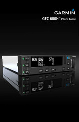
Garmin GFC 600H Pilot's Manual (74 pages)
Brand:
Garmin
| Category:
Avionics Display
| Size: 1 MB
Table of Contents
Table of Contents
9
Section 1 System Overview
11
Basic Functions
11
HFCS Equipment
12
GMC 605H Mode Controller
12
GFS 83 Servo
13
Attitude and Air Data Sensors
14
HFCS Controls
16
GMC 605H (3-Axis)
16
External Controls
17
System Indications
20
Gmc 605H
20
Garmin PFD HFCS Indications
22
Section 2 Helicopter Flight Control System
25
HFCS Operation
25
HFCS Pre-Flight
25
Engaging the Helicopter Flight Control System
26
Disengaging the Helicopter Flight Control System
26
Flight Director Modes
27
Basic Helicopter Flight Control System Features
30
Attitude Hold Mode (ATT)
30
Vertical Flight Director Modes
33
Vertical Flight Director Mode Controls and Annunciations
33
Altitude Hold Mode (ALT)
34
Selected Altitude Capture Mode (ALTS)
35
Vertical Speed Mode (VS)
37
Indicated Airspeed Mode (IAS)
38
Glidepath Mode (GP)
39
Glideslope Mode (GS)
41
Lateral Modes
43
Lateral Mode Controls and Annunciations
43
Heading Select Mode (HDG)
44
Navigation Modes (GPS, VOR, LOC, BC)
45
Approach Modes (GPS, VAPP, LOC)
47
Flying an Arc with a GPS Navigator
50
Visual Approaches
51
Helecopter Electronic Stability & Protection (H-ESP™)
51
Limit Cueing
52
Overspeed Protection
54
Low Speed Protection
56
Section 3 Annunciations & Alerts
59
Visual Annunciations and Alerts
59
GMC 605H Annunciations
59
PFD Visual Annunciations and Alerts
62
Aural Alerts
63
Voice Alerts
63
Flight Control System Disconnect Alert
64
Section 4 Abnormal Operation
65
Suspected Flight Control System Malfunction
65
Section 5 Terms & Conventions
67
Equipment Terminology
67
System Operation Terminology
67
Helicopter and System Controls
69
Flight Director Modes
70
Section 6 Index
73
Advertisement
Garmin GFC 600H Pilot's Manual (62 pages)
Brand:
Garmin
| Category:
Control Systems
| Size: 1 MB
Table of Contents
Table of Contents
7
Section 1 System Overview
9
Basic Functions
9
HFCS Equipment
10
GMC 605H Mode Controller
11
GFS 83 Servo
11
Attitude and Air Data Sensors
12
HFCS Controls
14
GMC 605H (3-Axis)
14
External Controls
15
System Indications
17
Gmc 605H
17
Garmin PFD HFCS Indications
20
Section 2 Helicopter Flight Control System
21
HFCS Operation
21
HFCS Pre-Flight
21
Engaging the Helicopter Flight Control System
22
Disengaging the Helicopter Flight Control System
22
Upper Modes
23
HFCS Operation Limitations
24
Basic Helicopter Flight Control System Features
24
Attitude Hold Mode (ATT)
24
Vertical Coupled Modes
27
Vertical Coupled Mode Controls and Annunciations
27
Altitude Hold Mode (ALT)
28
Selected Altitude Capture Mode (ALTS)
29
Vertical Speed Mode (VS)
30
Indicated Airspeed Mode (IAS)
31
Glidepath Mode (GP)
31
Glideslope Mode (GS)
33
Lateral Coupled Modes
34
Lateral Coupled Mode Controls and Annunciations
34
Heading Select Mode (HDG)
35
Navigation Modes (GPS, VOR, LOC)
36
Approach Modes (GPS, VAPP, LOC)
38
Flying an Arc with a GPS Navigator
41
Helicopter Electronic Stability & Protection (H-ESP™)
41
Limit Cueing
42
Overspeed Protection
44
Low Speed Protection
45
Section 3 Annunciations & Alerts
47
Visual Annunciations and Alerts
47
3-Color LED
47
GMC 605H cas Messages
48
GMC 605H Annunciations
50
Aural Alerts
51
Voice Alerts
51
Flight Control System Disconnect Alert
52
Section 4 Abnormal Operation
53
Suspected Flight Control System Malfunction
53
Section 5 Terms & Conventions
55
Equipment Terminology
55
System Operation Terminology
55
Helicopter and System Controls
57
Mode Annunciations
58
Section 6 Index
61
Advertisement
Related Products
Garmin G1000 Series
Garmin GFC 700
Garmin GFC 500
Garmin GFC 600
Garmin GFS 10 - Fuel Sensor
Garmin GFH013R - MapSource Fishing Hot Spots
Garmin GFH014R - MapSource Fishing Hot Spots
Garmin GFH022R - MapSource - Recreational Lakes
Garmin GFL 10
Garmin GA-WT-VENU3S-010-02785-01
Garmin Categories
GPS
Watch
Car Navigation system
Avionics Display
Marine Equipment
More Garmin Manuals
Login
Sign In
OR
Sign in with Facebook
Sign in with Google
Upload manual
Upload from disk
Upload from URL