Sign In
Upload
Manuals
Brands
Gardner Denver Manuals
Air Compressor
VS-11
Gardner Denver VS-11 Manuals
Manuals and User Guides for Gardner Denver VS-11. We have
1
Gardner Denver VS-11 manual available for free PDF download: Operating And Service Manual
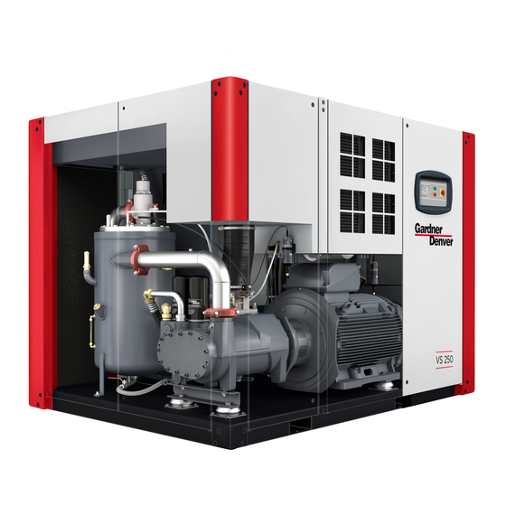
Gardner Denver VS-11 Operating And Service Manual (68 pages)
VARIABLE SPEED SINGLE STAGE STATIONARY BASE-MOUNTED COMPRESSOR
Brand:
Gardner Denver
| Category:
Air Compressor
| Size: 2 MB
Table of Contents
Maintain Compressor Reliability and Performance with Genuine Gardner Denver Compressor Parts and Support Services
2
Instructions for Ordering Repair Parts
2
Warning - Prohibition - Mandatory Label Information
3
Safety Precautions
5
Table of Contents
6
Index
7
List of Illustrations
8
Section 1, General Information
9
Figure 1-1 - Compression Cycle
9
Figure 1-2 - Package Outline (Air-Cooled)
10
Figure 1-3 - Package Outline (Air-Cooled)
11
Figure 1-4 - Package Outline (Air-Cooled) - Tank Mounted
12
Figure 1- 5 - Package Outline (Air-Cooled) - Tank Mounted
13
Section 2, Installation
14
Figure 2-1 - Recommended Lifting Modes
14
Figure 2-2 - Typical Compressor Room
15
Figure 2-3 - Package Maximum Current Consumption Summary
18
Figure 2-4 - Line Reactor Sizing Recommendations
19
Section 3, Starting & Operating Procedures
20
Section 4, Controls & Instrumentation
27
Figure 4-1 - Electrical Enclosure Hardware
28
Figure 4-2 - Piping and Instrumentation Illustration
31
Figure 4-3 - Wiring Diagram - (Air-Cooled) Single-Stage VS Control
32
Figure 4-4 - Wiring Diagram - (Air-Cooled) Single-Stage VS Control
33
Figure 4-5 - Wiring Diagram - (Air-Cooled) Single-Stage VS Control
34
Figure 4-6 - Wiring Diagram - (Air-Cooled) Single-Stage VS Control
35
Section 5, Compressor Lubrication - Separation, Filtration and Controls
36
Figure 5-1 - Checking Oil Level
38
Figure 5-2 - Oil Mixing Valve (Thermostatic) Hardware
41
Figure 5-3 - Pressure Dew Point of Compressed Air
41
Figure 5-4 - Changing Oil Coalescing Element
43
Section 6 - Heat Exchangers (Oil, Air)
44
Figure 6-1 - Air Flow Chart
45
Figure 6-2 - Cleaning Cooler Core
46
Figure 6-3 - Water Separator and Drain
46
Section 7, Air Filter
48
Figure 7-1 - Air Filter (Standard)
48
Section 8, Shaft Coupling
50
Figure 8-1 - V-Belt Assembly
50
Figure 8-2 - Motor Sheave and Bushing
51
Figure 8-3 - Motor Sheave/Bushing Fastener Torque
51
Figure 8-4 - Compressor Sheave and Sleeve Servicing
52
Section 9, Minimum Pressure/Check Valve
53
Figure 9-1 - Minimum Discharge Pressure/Check Valve
54
Section 10, Inlet Control Valve
55
Figure 10-1 - Inlet Control Valve
55
Section 11, Pressure Relief Valve
57
Figure 11-1 - Pressure Relief Valve
57
Section 12, Ventilation Fans, Filters (Electrical Enclosure)
59
Figure 12-1 - Ventilation Filter Assembly
59
Section 13, Motor Lubrication
60
Section 14, Maintenance Schedule
61
Section 15, Troubleshooting
63
Advertisement
Advertisement
Related Products
Gardner Denver AirSmart VS135A
Gardner Denver AirSmart VS170
Gardner Denver AirSmart VS170A
Gardner Denver VS110A
Gardner Denver VS70A
Gardner Denver VST180A
Gardner Denver AirSmart VS20A
Gardner Denver VST225-260A
Gardner Denver VS80A
Gardner Denver VST110-180B
Gardner Denver Categories
Air Compressor
Water Pump
Dehumidifier
Controller
Compressor
More Gardner Denver Manuals
Login
Sign In
OR
Sign in with Facebook
Sign in with Google
Upload manual
Upload from disk
Upload from URL