Sign In
Upload
Manuals
Brands
galvanic Manuals
Measuring Instruments
943-TGX
galvanic 943-TGX Tail Gas Analyzer Manuals
Manuals and User Guides for galvanic 943-TGX Tail Gas Analyzer. We have
1
galvanic 943-TGX Tail Gas Analyzer manual available for free PDF download: Operation Manual
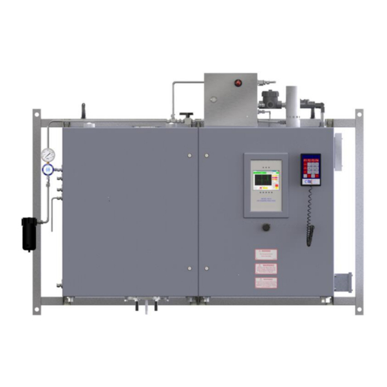
galvanic 943-TGX Operation Manual (148 pages)
Hybrid Automatic Process UV Spectrophotometer for Tail Gas Analysis
Brand:
galvanic
| Category:
Measuring Instruments
| Size: 8.02 MB
Table of Contents
Table of Contents
3
Repaired Products
13
Limitation of Remedy and Liability
13
943-Tgx
14
Analytical Method
14
Overview
14
Analyzer Design
15
Figure 1: Model 943-TGX (Hybrid)
16
Sample Handling System
16
Contents of this Manual
17
System Operating Control
17
Section 2 Installation
19
Receiving the System
19
Environmental Requirements
19
Electrical Requirements
19
Space Requirements
19
Table 1: Ambient Temperature Range by Model
19
Temperature
19
Area Classification
20
Instrument Air
20
Steam
20
Unpacking
20
Table 2: Steam Supply Requirements
20
Installation Procedure
21
Figure 2: Mounting Dimensions
22
Mounting of the Analyzer System
22
Figure 3: Service Connections
23
Mating of the Process and Analyzer System Flanges
23
Figure 4: Hole Plug in Oven Cabinet Removed
24
Installation of the Sample Probe
24
Figure 5: Oven Enclosure Tubing Removed
25
Figure 6: Inserting the Sample Probe
25
Figure 7: Oven Enclosure Tubing Reinstalled
26
Connection of the AC Power Service
27
Connection of the Analog Signal Cables
27
Figure 8: Location of Acts in Control Cabinet
27
Connection of the Digital Signal Cables
28
Figure 9: Location of Analog Output Terminals on Io Board
28
Connection of the Instrument Air
29
Figure 10: Location of Digital Output Terminals on Io Board
29
Figure 11: Location of Instrument Air Regulator
30
Figure 12: Control Cabinet Purge Control Box
30
Connection of the Loss of Purge Signal
31
Connections of Steam
31
Section 3 Operation
32
Overview
32
Figure 13: Location of Air Flow Control Valves in Oven Cabinet
32
Flow Control Settings
33
Cabinet Purge Air Flow Adjust Valve
33
Figure 14: Sample System Flow Diagram
33
Cabinet Cooler Air Valve
34
Figure 15: Location of Vortex Cooler
34
Condenser Cooling Air Flow Adjust Valve
35
Figure 16: Sample Probe
35
Zero Air Flow Adjust Valve
36
Aspirator Drive Air Flow Adjust Valve
37
Figure 17: Measurement Cell Block (Exploded View)
37
System Regulator
38
Analyzer Outputs
38
Analog Outputs
38
Digital Outputs (Relays)
39
Status
39
Table 3: Status Relay States
39
Mode
40
Service
40
Table 4: Service Relay States
40
Table 5: Mode Relay States
40
Control
41
Loss of Purge
41
Table 6: Control Relay States
41
Section 4 Local System Control
43
Overview
43
Using the Local Display and Handheld Keypad
43
Figure 18: Local Display User Interface
43
Local Display User Interface
43
Figure 19: Handheld Keypad
44
Table 7: Keypad Red Key Functions
44
The Handheld Keypad
44
Analysis 1 Panel
45
Concentration Fields
45
Figure 20: Online / Offline Mode Toggle
45
Online/Offline Mode Toggle
45
Air Demand
46
Figure 21: Analysis 1 Concentration Fields
46
Figure 22: Air Demand Value and Trend
46
Figure 23: Relay Indicators
47
Figure 24: Manual Zero Control
47
Manual Zero
47
Relay Indicator Fields
47
Back Purge Indicator and Control
48
Analysis 2 Panel
49
Figure 25: Back Purge Indicator and Manual Controls
49
Figure 26: Analysis 2 Panel
49
Concentrations, Air Demand, and Trend Graph
50
Figure 27: Online / Offline Control
50
Figure 28: Data Fields and Trend Graph
50
Online / Offline Control
50
System Operating Parameters
51
Indicators Panel
51
Figure 29: System Operating Parameters
51
Table 8: System Operating Parameters
51
Figure 30: Indicators Panel
52
Fault Conditions
53
Table 10: Analyzer Warnings
53
Table 9: Analyzer Faults
53
Warning Conditions
53
Spectrum Panel
54
Figure 31: Spectrum Panel
54
Figure 32: Spectrometer Parameters
54
Table 11: Spectrometer Parameters
55
Factory Reference
56
Figure 33: Integration Period Dialog Box
56
Figure 34: Factory Reference
56
Absorbance Panel
57
Figure 35: Absorbance Panel
57
Figure 36: Absorbance Spectrum for H 2 S
58
Figure 37: Absorbance Spectrum for so 2
58
Config Panel
59
Figure 38: Outputs Sub-Panel
59
Outputs
59
Table 12: Analog Output Parameters
60
Calculation Parameters
61
Calculation Sub-Panel
61
Figure 39: Calculation Sub-Panel
61
Cell Length
62
Table 13: Calculation Parameters
62
Analysis 1 and 2 Trend Graph Ranges
63
Display
63
Figure 40: Display Sub-Panel
63
Fixed Temperature and Pressure
63
Sample and Zero Sample Rate
63
Backlight Adjustment
64
Figure 41: Timers / Alarms Sub-Panel
64
Timers/Alarms Sub-Panel
64
Table 14: Timers Parameters
65
Temperature Control
65
Timers
65
Table 15: Temperature Control Parameters
66
Alarms
67
Table 16: Alarms Parameters
67
Direct Connect
68
Figure 42: Network Sub -P
68
Network
68
Network Sub Panel
68
Figure 43: Controller Board
69
Section 5 Web - Based Graphical User Interface (Gui)
70
Overview
70
Figure 44: Brimstone Web
70
Analysis Section
71
Analysis Page
71
Figure 45: Navigationm
71
Figure 46: Analysis Section
72
Table 17: Value Display Parameters
72
Value Display
72
Relay Indicators
73
Status and Control
73
Table 18: Status and Control
73
Air Demand and H2S/SO2 Trends
74
Table 19: Relay Indicators
74
Calibration Matrix Page
75
Figure 47: Trend Graph Y-A
75
Figure 48: Spectrometer
75
Figure 49: Calibration Matrix
76
Indicators Page
76
Figure 50: Indicators Page
77
Table 20: Analyzer Faults
77
Figure 51: Spectrum Page
78
Spectrum Page
78
Table 21: Analyzer Warnings
78
Figure 52: Spectrum Curve
79
Table 22: Spectrum Parameters
79
Absorbance Page
80
Figure 53: Set Integration
80
Figure 54: Absorbance Page
81
Figure 55: Absorbance Curve
81
Figure 56: Absorbances
82
Figure 57: Absorbances
82
Configuration Section
83
Figure 58: Configurationp
83
Parameters Page
83
Table 23: Parameters Page Colour Code
83
Table 24: Configuration Parameters
84
Figure 59: Login Dialog Box
85
Figure 60: Modbus Page
86
Modbus Page
86
Table 25: Modbus Communication Parameters
87
Figure 61: Modbus Typed
88
Table 26: Available Modbus Points
88
Enron Modbus Format
89
Figure 62: Editing a Modbus
89
Table 27: Modbus List Columns
89
Figure 63: Enron Modbusf
90
Figure 64: Modicon 16 Format
90
Modicon 16 Format
90
Modicon with Floating Point Format
91
Factory Section
91
Figure 65: Modicon 32 Format
91
Table 28: Factory Parameters Colour Code
92
Table 29: Factory Parameters
92
Changing the Passwords
94
Help Section
94
Drawing Page
94
Figure 67: Change Password
94
Figure 68: Password Entry
94
Figure 69: Revision History
95
Revision History Page
95
User Manual Page
95
Section 6 Maintenance
96
Overview
96
Routine Preventative Maintenance
96
Visual Inspection of Key Operating Parameters
96
Maintenance Check out Procedure
97
Table 30: Normal Operating Parameter and Indicator Conditions
97
Table 31: Maintenance Record Sheet
99
Changing the Anti-Solarant Solution
100
Figure 70: Replacing Thea
101
Optimizing the Spectrometer Signal
102
Automated Optimization
103
Manual Optimization
103
Section 7 Service
105
Overview
105
Indicators Panel Troubleshooting
105
Figure 71: Indicators Panel
105
Table 32: Analyzer Fault / Warning Troubleshooting
106
Testing and Replacement of the Optical Fibres
107
Figure 72: Location of Cell
108
Troubleshooting the Uv Source Lamp
110
Table 33: Lamp Troubleshooting
111
Figure 73: Uv Lamp Enclosure
112
Figure 74: Uv Lamp Enclosure
113
Figure 75: Uv Lamp Orientation
113
Measurement Cell Block Removal
115
Cell Windows Cleaning / Replacement
116
Figure 76: Oven Enclosure
116
Figure 77: Measurementc
117
Measurement Cell Installation
119
Steam Purging the Sample Probe
120
Spectrometer Replacement
122
Figure 78: Spectrometer
122
Figure 79: Utility Page
124
Figure 80: Spectrometerc
124
Section 8 the Product Quality Assurance Program
126
Overview
126
Overall System Identification
126
Qa Document Package Check List and Requirements
127
Table 34: Document Package Checklist
127
Figure 81: Mounting Ands
128
Section 9 Drawings
128
Figure 82: Oven Cabinetd
129
Figure 83: Control Cabinet
130
Figure 84: Power , Steam , a
131
Figure 85: Ac Wiring Schematic
132
Figure 86: DC Signals Andw
133
Figure 87: Flow Diagram
134
Section 10 Specifications
135
Section 11 Recommended Spare Parts
136
Table 35: Recommended Spare Parts - 1 Year Kit
136
Table 36: Recommended Spare Parts - 2 Year Kit
136
Section 12 Input / Output (Io) Board Configuration
137
Io Board Web Gui
137
Figure 88: Io Board Web
137
Status Page
138
Figure 89: Status Page
138
Table 37: IO Board Web GUI Pages
138
Manual Override Page
139
Table 38: Status Page Sections
139
Analog Output Calibration and Testing
140
Figure 90: Manual Override
140
Figure 91: Analog Outputt
141
Testing Digital Outputs
142
Testing the Digital Input
142
Figure 92: Relay Connection
143
Index
144
Advertisement
Advertisement
Related Products
galvanic 943-TGXeNA
galvanic Categories
Measuring Instruments
Accessories
More galvanic Manuals
Login
Sign In
OR
Sign in with Facebook
Sign in with Google
Upload manual
Upload from disk
Upload from URL