Sign In
Upload
Manuals
Brands
Gallagher Manuals
Power Supply
PULSE Series
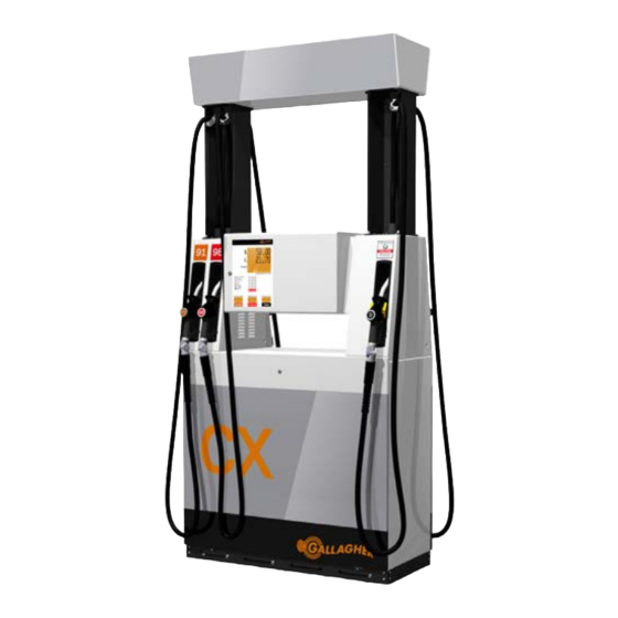
Gallagher PULSE Series Manuals
Manuals and User Guides for Gallagher PULSE Series. We have
1
Gallagher PULSE Series manual available for free PDF download: Installation Manual
Gallagher PULSE Series Installation Manual (136 pages)
Brand:
Gallagher
| Category:
Power Supply
| Size: 13 MB
Table of Contents
Table of Contents
3
Part A: General
8
About this Manual
8
Notations
8
Pictograms
8
Safety Warnings & Precautions
9
Hazard Warnings
9
Damage Warnings
10
Information Relating to DEF (Diesel Exhaust Fluid)
10
Materials Not Recommended to be Used with DEF
11
Greasing Threaded Connections
11
Figure 1 Greasing Threaded Connections
11
Fastening of Panel Screws
12
Figure 2� Location of Panel Screws
12
General Shipping & Transportation Information
13
Handling
13
Storage
14
Pulse Technical Specifications
15
Part B: Installation
16
Lifting of Units
16
Prior to Installing
16
Underpump Containment Sump
16
Hydraulic Pre-Installation
16
Anchoring Bases
16
Figure 3� Anchor Point Locations
17
Electrical Requirements/Regulations
18
Hydraulics
19
Pumps
19
Dispensers
19
Lpg
19
Vapour Recovery
19
Series Hose Installation (Hanging)
20
Remove the Holsters
20
Fit the Spreader
20
Fit the Hoses
21
Replace the Holsters
22
Series Hose Installation (Retractor)
23
Remove the Spreader Panels
23
Prepare Spring Reel Cable for Connection to Hose
24
Remove Holster Panels to Allow Access to Hoses
24
Connect the Hoses
25
Attach the Hose Clamp to the Hose and Retractor Cable
26
Refit Panels
27
Nozzle Switch Connection
28
Correct Fitting of Hoses to Hi-Arm
28
Figure 4� Correct Nozzle Switch Connection
28
Figure 5� Correct Method of Fitting Hoses to High-Arm
28
Bennett Pump Unit
29
Pre-Installation Check of Rotor Movement
30
Realignment Procedure
30
Belt Tension
30
Vacuum and Pressure Testing
30
Electrical
31
General
31
Mains
31
Comms
31
Figure 7� Single Phase Pump Connector Blocks
31
Mains Connections
32
Figure 9� Comms Connections
32
Forecourt Communications
33
Figure 10� Location and Positioning of Protocol Pins
33
Figure 11� Central Controller DCE
33
Float Switch Installation
34
Figure 12� Float Switch Installation
34
Installing the Head Lighting
35
Figure 13� Head Lighting Assembly
35
Rear Side of the Head
35
Connecting the Light Cable for the Illuminated Spreader
38
Part C: Commissioning
39
Overview
39
Figure 15� Overall Commissioning Process
39
Safety Inspection
40
System Start-Up Checks
40
Lpg Trade Measurement Verification Process
40
Service Mode Settings
40
Calibration
41
Firmware Test
41
Adjustment Wheel
41
Lobe Meter (Ultra Diesel)
42
Calibration Procedure
42
Lobe Meter
42
Encoder PCB
42
Calibration Procedure for Blending Units
43
Lpg Section
44
LPG Stack Components
45
Figure 19� LPG Stack Components
45
4-Way Meter Feed Valve Settings
46
Return Line Valve
46
Figure 20� Meter Feed Valve Settings
46
Figure 21� Return Line Valve with LPG Nozzle Attached
46
LPG Stack Test - Version 1.11
47
LPG Stack Test - Version 1.20
48
LPG Trade Measurement Verification Process - Version 1.11
49
Figure 22� Location of Dipswitches
49
LPG Trade Measurement Verification Process - Version 1.20
51
LPG Meter Calibration - Version 1.20
52
LPG Electrical Schematics
53
Figure 23� LPG Electrical Schematic
53
Figure 24� LPG Electrical Schematic Using Integrated Stack Controller
53
Part D: Servicing
54
General Care and Maintenance
55
Daily Maintenance
55
Monthly Maintenance
55
Annual Maintenance
55
Target Torques for Gasket Sealing
56
Figure 25� Target Torques for Gasket Sealing
56
Nozzles
57
Elaflex (Petrol/Diesel)
57
Figure 26� Elaflex ZVA Slimline 2 Nozzle
57
Elaflex GG1DN / LPG
58
Elaflex DEF Nozzles
59
Safety Breaks
60
Figure 28� Elaflex SSB Safety Break
60
Lpg Dry Breaks
61
Hoses
62
Figure 29� Brass Swivel Nuts and Hose Clamp
62
Figure 30� Gaining Access by Moving the Channel Runners
62
Shortening Hoses
63
Asco 24V Proportional Valve
64
Figure 31� ASCO Proportional Valve
64
Maintaining the Spring Reel Tension (L Series)
65
Replacing the Pump Unit / Air Separator Strainers
66
To Replace the Inlet Strainer
66
To Replace the Outlet Strainer
67
Def Filter Cartridge Replacement
68
Figure 32� Filter Housing and y Strainer
68
Figure 33� Removal of the Filter Housing
68
Electrical
69
Remounting a PULSE UI Battery Pack
69
Figure 34� Shield Surface with BUP Board and Battery Pack
69
Simple Wiring Diagram
70
Figure 35� Simplified Wiring Diagram
70
Junction Box Wiring Diagrams
71
Figure 37� Comms Connections
71
Sd Card Content
72
Process for Loading Firmware Onto the SD Card
72
Configuration Reinstall
72
Obtaining Dispenser Logs
73
Service Mode Functions
73
Entering Service Mode
73
SD Card Setting
73
Service Mode Function Screens
73
Figure 38� Order of Service Mode Screens
73
Firmware - FIRMW
74
Setting VR Active - VRCTRL
75
Setting Pump Numbers - CGFPID
75
Setting a Password - CGPWD
76
Errors - ERRORS
77
Setting Hoses Active/Inactive - HOSE
78
Grade Priority - PRIORTY
78
5/6 Digit Mode - 5DIGIT
78
Pos/Standalone - POS
79
Grade Prices - PRICE
79
Hydraulic Stack Test - STACK
80
Checking Input Status
81
View/Set Date & Time
82
Maintaining Isolation of Mains Voltage Within Head Cabinet
82
Manager & View Totes Modes - All Versions
83
Manager Mode
83
View Totes Mode
83
Service Mode Functions
84
Summary of New Key Features and Functions
84
Entering Service Mode
85
Service Mode Function Screens - Version 1�20
85
Figure 39� Order of Service Mode Screens
85
SD Card Setting - SDCARD
86
Stack Menu - STK MENU
86
Setting Pump Numbers - FP ID
88
Point of Sale Menu - POS
89
Grade Priority - MAPPING
90
Setting Hoses Active/Inactive - HOSE
91
Grade Prices - PRICE
91
LPG Menu
92
Errors - ERRORS
94
PULSE Counted Error Codes
95
Timeout Menu - TIMEOUT
96
Start-Up Delay - STARTDEL
97
Flow Control - FLOWCTRL
97
View/Set Time - TIME
98
View/Set Date - DATE
98
Setting a Password - PASSWD
99
Setting VR Active - VR2
99
Totes
100
Reload Configuration - CONFIG
100
Restart Central Controller - REBOOT
100
Operating System Menu - os
101
Firmware - FIRMWARE
102
Hydraulic Stack Test (Blending)
104
Procedure
104
Testing the Non-Return Valves (Circled in Diagrams)
106
Adjusting Flow Rates
106
Calibration
107
Flow Control - FLOWCTRL
107
Grade Priority - MAPPING
107
Setting Hoses Active/Inactive - HOSE
107
Ratio Error
107
Addressing Lpg Meters - Version 1�20
108
Pulse Media
111
Figure 41� PULSE Media Components
111
Operation
112
Power Buttons
112
Figure 42� Windows Keyboard
112
Figure 43� Location of Power Buttons for Media Player and LCD Screen
112
Adjusting the Volume
113
Electrical Protection
113
Wiring Diagram
113
Cleaning the LCD Screen
113
Figure 46� PULSE Media Basic Wiring Diagram
113
Troubleshooting
114
Dispenser will Not Deliver Fuel
114
Dispenser will Deliver Fuel
116
Quick Reference Guide - Version 1�11
117
Quick Reference Guide - Version 1�20
118
Appendix - Blending Information
119
Flow
119
Layout
120
Blending Manifold
121
Wiring
121
Stack Controllers
121
Figure 49� Blending Manifold Assembly
121
Multiplexers
122
Figure 51� Wiring Positions of the Stack Controller
122
Figure 52� Wiring Positions of the Multiplexer Board
122
Appendix - Dispenser Control Systems
123
Figure 55� 3-Board Stack Controller
125
Figure 56� DC Integrated Stack Control - 1
126
Figure 57� DC Integrated Stack Control - 2
127
Figure 58� AC Integrated Stack Control
128
Figure 59� 1 or 2 User Interface Modules
129
Figure 60� 3 or 4 User Interface Modules
130
Figure 61� Multiplexer Board Detail
131
Figure 62� VR2 Subsystem Detail
132
Advertisement
Advertisement
Related Products
Gallagher PowerBox
Gallagher 346304
Gallagher 360300
Gallagher 389318
Gallagher 390307
Gallagher 390314
Gallagher 3E0708 Master Series
Gallagher 3E1773
Gallagher Categories
Power Supply
Scales
Card Reader
Farm Equipment
Battery Charger
More Gallagher Manuals
Login
Sign In
OR
Sign in with Facebook
Sign in with Google
Upload manual
Upload from disk
Upload from URL