Sign In
Upload
Manuals
Brands
Fukuda Denshi Manuals
Medical Equipment
VaSera VS-1500
User Manuals: Fukuda Denshi VaSera VS-1500 Device
Manuals and User Guides for Fukuda Denshi VaSera VS-1500 Device. We have
1
Fukuda Denshi VaSera VS-1500 Device manual available for free PDF download: Service Manual
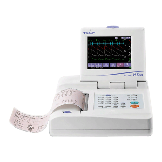
Fukuda Denshi VaSera VS-1500 Service Manual (216 pages)
Brand:
Fukuda Denshi
| Category:
Medical Equipment
| Size: 6 MB
Table of Contents
Table of Contents
8
Chapter 1 Features
13
Features
14
What the Instrument Can Do
14
Major Features
14
Examination Mode
16
Chapter 2 Specifications
19
VS-1500N Specifications
20
Chapter 3 Composition of the Product
21
Accessories
22
Vs-1500N
22
ECG Upgrade Package
24
ECG Accessories Package
24
Optional Accessories
25
Chapter 4 Names of Parts of Equipment
27
Front
28
Rear
29
Bottom
30
Operation Panel
31
Chapter 5 Maintenance
33
Replacing Lithium Battery for Maintaining Clock and Settings
35
Cleaning and Disinfecting
36
Cleaning and Disinfecting the Enclosure
36
Cleaning the Built-In Recorder
36
Cleaning the Display Unit
36
Cleaning the Accessories
37
Self-Diagnosis (User Maintenance)
38
Checking Instrument Status
38
Testing Built-In Thermal Array Recorder
40
Complete I/O Test
43
Testing LAN Communications
44
Testing Serial Communications
44
Testing CF Card
45
Testing Printer Connection
45
Testing SRAM
46
Testing Program Cartridge Connection
46
Testing Pump Unit
47
Adjusting the Touch Panel
49
Confirming Pressure Accuracy
50
Testing PC Connection
52
Testing Operation Panel Fixed Keys
53
Testing the Display
54
Testing Sound and Tone
55
Testing the Touch Panel
56
Initializing Set Values
57
Making VS-1000 CF Cards Usable on the VS-1500
57
Uninstalling ECG
57
Self-Diagnosis (Manufacturer Maintenance)
58
Recording Various Waveforms Manually
59
Checking Cuff Pressure
61
Performing Automatic Tests
62
Adjusting Mark Sensor
63
Referencing the Register
63
Installation
64
Installing Software
64
Boot (Installation Software) Program Installation
64
Installing Standard 12-Lead ECG Testing Software
65
Adjusting the Built-In Thermal Array Recorder
67
Maintenance of the Color Printer
68
Loading the Paper
68
Maintenance Function
69
Replacing the Print Cartridge
70
Optional Accessories
72
Replacing the Fuse on the Printer Shelf
72
Maintenance and Inspection
73
About Maintenance and Inspection
73
Daily Inspection Procedure
74
Periodic Inspection Procedure (1)
76
Periodic Inspection Procedure (2)
78
Safety Inspections
83
Daily Check List
90
Periodic Check List (1)
91
Periodic Check List (2)
92
Chapter 6 Troubleshooting
95
Power Supply
96
Built-In Thermal Array Recorder
97
Blood Pressure
100
Ecg
102
PCG and Pulse Waves
103
Fixed Keys/Touch Panel
104
Display
105
CF Cards
106
LAN Communications
108
Color Printer
109
Serial Communications
111
Other Functions
112
Chapter 7 Messages
113
Messages and Countermeasures
114
Instrument and Measurement-Related Messages
114
CF Card-Related Messages
116
Color Printer Related Messages
117
Personal Computer-Related Messages
117
Chapter 8 Disassembly and Assembly
118
Instrument Disassembly
119
Removing the Upper and Lower Cases
119
Removing the Main Board
120
Removing the Pump Block
123
Removing Recorder and Power Supply Unit
124
Removing the LCD
125
Removing the Keyboard
127
Instrument Assembly
128
Main Block Assembly
128
Lower Case Assembly Drawing
132
LCD Unit (Rear) Assembly Drawing
134
Upper Case Assembly Drawing
135
General Assembly Drawing
140
Assembly of the Trolley OTV-01
141
Parts List
141
Assembly Procedure
142
Installation of the Cuff Holder OAV-01A
145
Parts List
145
Installation Procedure
145
Installation of the Printer Shelf OAV-03A
146
Parts List
146
Installation Procedure
146
Installation of the Cable Hanger OA-300A
150
Parts List
150
Installation Procedure
150
Caution
152
Chapter 9 Wiring Diagrams, Block Diagrams with Descriptions and Connector Pin Locations
154
Definitions of Symbols Used in this Document
155
Connecting Diagram
156
Upper Case
156
Lower Case
157
Block Diagram and Description
158
Main Board
158
Cuff Board /Pump Unit
161
LCDTP if Board
162
Other Functions
163
Connector Pin Arrangement
164
Main Board
164
Cuff Board
170
Lcdtp if Board
171
Cartridge if Board
172
Key Board
172
Lcd Sw Board
172
Inverter
173
LCD Module
173
External Connector
174
Chapter 10 Part Location Diagram and Checkpoints
177
Main Board
177
MAIN BOARD Part Location Diagram (Component Side)
177
MAIN BOARD Part Location Diagram (Soldering Side)
179
Main Board Checkpoints
181
Cuff Board
187
Part Location Diagram
187
Power Supply and Test Pin Checks
187
Lcdtp if Board
189
Part Location Diagram
189
Power Supply and Signal Checks
189
Power Supply Unit
190
Output Voltage Check
190
Chapter 11 Spare Parts List
192
Replacement of the Accessories
193
Main Unit
194
Upper Case Block
195
LCD Block
196
Lower Case Block
197
Pump Block
198
Main Block
199
LCD Unit
200
Part Block Diagram
201
Upper Case Block
201
Accessories
204
Optional Accessories
205
Consumables
206
Chapter 12 Information of the Electromagnetic Compatibility (EMC)
208
Guidance to Electromagnetic Compatibility
209
Electromagnetic Emission Compatibility
209
Compatibility with Electromagnetic Immunity (1)
210
Compatibility with Electromagnetic Immunity (2)
211
Recommended Separation Distance between Portable or Mobile RF Communication Equipment and the VS-1500
212
Interference Generated by Electrical Scalpels
212
Advertisement
Advertisement
Related Products
Fukuda Denshi VaSera Series
Fukuda Denshi VSS-50
Fukuda Denshi 4R2043
Fukuda Denshi CARDIMAX FX-7202
Fukuda Denshi CardiMax FX-8322
Fukuda Denshi CardiMax FX-8322R
Fukuda Denshi CardiMax8
Fukuda Denshi DS-7001
Fukuda Denshi DS-8200
Fukuda Denshi DS-8400
Fukuda Denshi Categories
Medical Equipment
Monitor
Transmitter
Measuring Instruments
Control Unit
More Fukuda Denshi Manuals
Login
Sign In
OR
Sign in with Facebook
Sign in with Google
Upload manual
Upload from disk
Upload from URL