Sign In
Upload
Manuals
Brands
Fuji Electric Manuals
Control Unit
NP1F-HP2
Fuji Electric NP1F-HP2 Manuals
Manuals and User Guides for Fuji Electric NP1F-HP2. We have
1
Fuji Electric NP1F-HP2 manual available for free PDF download: User Manual
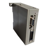
Fuji Electric NP1F-HP2 User Manual (135 pages)
PULSE TRAIN OUTPUT POSITIONING CONTROL MODULE
Brand:
Fuji Electric
| Category:
Control Unit
| Size: 0 MB
Table of Contents
Revision
6
Table of Contents
6
Section 1 General
8
Section 1 General
9
Precautions
9
Handling Precautions as Precision Device
9
Precautions Concerning Operating Conditions and Environment
9
Functional Overview
10
Overview of NP1F-HP2 Functions
10
Overview of NP2F-LEV Functions
11
Section 2 System Configuration
12
Configuration of Peripheral Equipment
13
Applied System
14
Applicable CPU
14
Applied System Configuration
14
Loader and Software Modules to be Used
15
Section 3 Specifications
16
General Specifications (NP1F-HP2)
17
General Specifications (NP2F-LEV)
18
Specifications (NP1F-HP2)
19
Specifications (NP2F-LEV)
19
Names
20
NP1F-HP2 (for 2 Axes)
20
NP2F-LEV (Signal Converter)
22
Dimensions
24
NP1F-HP2 (for 2 Axes)
24
NP2F-LEV (Signal Converter)
24
Section 4 Wiring
25
Mounting Precautions
26
Number of Mountable Modules (NP1F-HP2)
26
Wiring Precautions
27
Wiring Example of the External Wiring Connector
27
Connector Type
27
Connector Cover Type
27
Connector Pin Layout for the External Connection (NP1F-HP2)
28
External I/O Signal Specifications (NP1F-HP2)
29
Connector Pin Layout for the External Connection (NP2F-LEV)
36
External I/O Signal Specifications (NP2F-LEV)
37
External I/O Signal Interface (NP2F-LEV)
38
Connecting
40
Connecting Sample of a Servo Motor
40
When the NP1F-HP2 Generates the Forward Pulse or the Reverse Pulse
40
Forward Pulse Command, Reverse Pulse Command
40
Connecting Sample of FALDIC-II and NP1F-HP2
41
Connecting Sample of a Stepping Motor and NP1F-HP2
42
I/O Wiring
43
Section 5 Memory Map
44
NP1F-HP2 Memory Map (Internal Memory List)
45
I/O Area of NP1F-HP2
46
NP1F-HP2 (Read Area: Address No. 0 to No. 7)
47
Bit Data Signal (Status Signal, Lower Word, Ch1: Address No. 0, Ch2: Address No.4)
47
Bit Data Signal (Status Signal, Upper Word, Ch1: Address No. 1, Ch2: Address No. 5)
54
Current Value Area (Ch1: Address No. 2: Lower Word; Address No. 3: Upper Word, Ch2: Address No. 6: Lower Word; Address No. 7: Upper Word)
57
NP1F-HP2 (Write Area, Address Nos. 8 to 15)
58
Bit Command Signal (Write Signal, Lower Word Ch1: Address No. 8, Ch2: Address No. 12)
58
Bit Command Signal (Write Signal, Ch1: Address No. 9, Ch2: Address No. 13, Upper Word)
70
Set Value Area (Write Signal, Ch1: Address Nos. 10 and 11, Ch2: Address Nos. 14 and 15)
75
Setting Method and Effective Bits
76
Setting Method and Effective Bits
77
Section 6 Parameters (Registers)
79
Parameters (Registers)
80
Relationship between Parameters (Registers)
81
Detailed Description of Parameters (Registers)
83
Section 7 Positioning Function
99
Positioning Function of the Pulse Train Outputpositioning
100
Control Module (NP1F-HP2)
100
Control Method
100
Functions of Pulse Train Output Positioning Control Module (NP1F-HP2)
101
Command Pulse Count Control
102
Functions of Pulse Train Output Positioning Control Module (NP1F-HP2)
102
Command Pulse Frequency Control
103
Trapezoidal Acceleration/Deceleration
104
Automatic Deceleration Point Calculation
106
Deceleration Point Setting
106
Deceleration Point Setting
107
Continuous Frequency Rewriting
108
Setting Data to a Register
108
Data Reading from Register
109
Current Value Data Reading
110
Manual Operation
111
Original Point Return Motion
111
Positioning Operation
113
Interrupt Point Positioning Motion
114
Deceleration-And-Stop/Quick Stop Motion
115
Operation When an Emergency Stop Error Has Been Detected
116
Operation When an ± OT Error Has Been Detected
117
Command Pulse Counting
119
Operation When a Transmission Error Has Been Detected
120
Section 8 Troubleshooting
121
LED Indication
121
Error Indication
123
Appendix
127
Appendix-1 Parameters
128
Appendix-2 Memory Map
129
Appendix-3 Terminology
130
Appendix-4 Current Consumption and Mass of Modules in MICREX-SX Series
132
Advertisement
Advertisement
Related Products
Fuji Electric NP1AXH8V-MR
Fuji Electric NP1AYH8I-MR
Fuji Electric NP1AYH4V-MR
Fuji Electric NP1AWH6-MR
Fuji Electric NP1L-RS2
Fuji Electric T-link NP1L-TL1
Fuji Electric T-link NP1L-RT1
Fuji Electric T-link NP1L-TS1
Fuji Electric NP1L-RS3
Fuji Electric NP1L-RS1
Fuji Electric Categories
Air Conditioner
Inverter
Measuring Instruments
Controller
Control Unit
More Fuji Electric Manuals
Login
Sign In
OR
Sign in with Facebook
Sign in with Google
Upload manual
Upload from disk
Upload from URL