Sign In
Upload
Manuals
Brands
Fuji Electric Manuals
Inverter
FRN****E2S-7G series
Fuji Electric FRN****E2S-7G series Manuals
Manuals and User Guides for Fuji Electric FRN****E2S-7G series. We have
1
Fuji Electric FRN****E2S-7G series manual available for free PDF download: User Manual
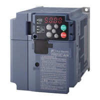
Fuji Electric FRN****E2S-7G series User Manual (788 pages)
high performance inverter
Brand:
Fuji Electric
| Category:
Inverter
| Size: 32 MB
Table of Contents
Table of Contents
5
Chapter 6 Troubleshooting
4
Table of Contents
5
Protective Function
17
Acceptance Inspection (Nameplates and Inverter Type)
21
External View and Terminal Blocks
23
Precautions for Using Inverters
25
Storage Environment
27
Precautions for Connection of Peripheral Equipment
28
Earth Leakage Circuit Breaker (ELCB)
29
Noise Reduction
30
Installation
33
Wiring
35
Removal and Attachment of the Front Cover/ Terminal Cover and Wiring Guide
38
Precautions for Wiring
40
Precautions for Long Wiring (between Inverter and Motor)
42
Main Circuit Terminals
44
Terminal Layout Diagram (Main Circuit Terminal)
47
Recommended Wire Size (Main Circuit Terminals)
49
Description of Terminal Functions (Main Circuit Terminal)
70
Control Circuit Terminals (Common to All Models)
74
Description of Terminal Functions (Control Circuit Terminal)
75
Switching Connector (Types FRN0203E2-4 or Above)
83
Operating Slide Switches
85
Attachment and Connection of Keypad
87
RJ-45 Cover
91
Operation Using the Keypad
93
Names and Functions of Keypad Components
95
Overview of Operation Modes
97
Running Mode
99
Monitoring Light Alarms
101
Running or Stopping the Motor
102
Setting up Reference Frequency from the Keypad
103
Setting up PID Commands from the Keypad
104
Settings under PID Dancer Control
106
Jogging Operation
108
Remote and Local Modes
109
Programming Mode
110
Setting up Basic Function Codes Quickly "Quick Setup: *Fnc "
132
Alarm Mode
134
Chapter 4 Test Run Procedure
135
Test Run Procedure Flowchart
137
Checking Prior to Powering on
138
Powering on and Checking
139
Destination Setting
140
Switching the Applicable Motor Rating (ND, HD, HND and HHD Modes)
142
Selecting a Desired Motor Drive Control
144
V/F Control with Slip Compensation Inactive for IM
144
Vector Control Without Speed Sensor (Dynamic Torque Vector) for IM
144
V/F Control with Slip Compensation Active for IM
145
V/F Control with Speed Sensor for IM
145
V/F Control with Speed Sensor with Auto Torque Boost for IM
145
Vector Control with Speed Sensor for IM
145
Vector Control Without Speed Sensor and Magnetic Pole Position Sensor for PMSM
146
Performance Comparison for Drive Controls (Summary)
147
Configuring Function Codes for Drive Controls
148
Driving an Induction Motor (IM)
149
1 ] Driving a Non-Fuji Motor or Fuji Non-Standard IM under the V/F Control
149
2 ] Driving a Fuji General-Purpose IM under the V/F Control
150
3 ] Driving an IM under the V/F Control with Speed Sensor
151
Speed Sensor
152
With/Without Speed Sensor
152
5 ] Driving a Fuji Dedicated IM (MVK Series) under Vector Control with Speed Sensor
156
Driving a Permanent Magnet Synchronous Motor (PMSM) Without Pole Sensor and
157
1 ] Driving a Non-Fuji PMSM
157
2 ] Driving a Fuji Dedicated PMSM (GNB2 Series)
162
3 ] Driving a Fuji Non-Dedicated PMSM (Non-GNB2 Series)
162
Running the Inverter for Motor Operation Check
163
Test Run Procedure
163
Check Points During a Test Run
163
Modification of Motor Control Function Code Data
164
Selecting a Frequency Command Source
166
Setting up a Frequency Command from the Keypad
166
Setting up a Frequency Command with an External Potentiometer
166
Setting up a Frequency Command with Multistep Frequency Selection
167
Selecting a Run Command Source
168
Setting up a Run Command from the Keypad
168
Setting up a Run Command with Digital Input Signals (Terminals [FWD] and [REV])
168
Chapter 5 Function Codes
169
Function Codes Overview
171
Function Codes Table
172
Supplementary Note
172
Function Codes Table
173
Function Codes Table
174
Factory Default Value Per Applicable Electric Motor Capacitance
206
(Function Code P99/ A39 = 0 or 4)
207
Motor Constants
207
2 ] When HP Rating Motor Is Selected by Motor Selection (Function Code P99/A39 = 1)
211
Description of Function Codes
215
F Codes (Basic Functions)
215
1 ] Frequency Setting by Keypad (F01 = 0 (Factory Default State), 8)
217
2 ] Setting up a Reference Frequency Using Analog Input (F01 = 1 to 3, 5)
218
3 ] Frequency Setting by Digital Input Signal "UP"/"DOWN" (F01=7)
224
4 ] Frequency Setting Using Digital Inputs (Option DIO Interface Card) (F01 = 11)
225
5 ] Frequency Setting Using Pulse Train Input (F01 = 12)
225
Torque Boost
255
E Codes (Extension Terminal Functions)
270
S Overspeed Protection
295
C Codes (Control Functions)
309
P Codes (Motor 1 Parameters)
318
H Codes (High Performance Functions)
325
Shipment
339
At Shipment
341
At Power Shutdown
342
A Codes (Motor 2 Parameters)
363
B, R Codes (Speed Control 3 and 4 Parameters)
366
J Codes (Applied Functions)
367
1 ] PID Command with the / Keys on the Keypad (J02 = 0, Factory Default)
368
2 ] PID Command by Analog Inputs (J02 = 1)
369
3 ] PID Command with UP/DOWN Control (J02 = 3)
371
4 ] PID Command Via Communications Link (J02 = 4)
371
5 ] Overload Stop Function
383
6 ] Brake Control Signal
384
7 ] Positioning Control with Pulse Counter
387
8 ] Servo Lock
396
D Codes (Applied Functions 2)
398
Speed Control
400
2 ] Master-Follower Operation
408
U Codes (Customizable Logic Operation)
418
Block Diagram
419
U1 Codes (Customizable Logic Operation)
443
Y Codes (Link Functions)
447
Chapter 6 Troubleshooting
453
Troubleshooting
453
Abnormal Motor Operation
454
Protective Function
455
Before Proceeding with Troubleshooting
456
The Motor Rotates, but the Speed Does Not Increase
456
If an Alarm Code Appears on the LED Monitor
457
Alarm Code List
457
1 ] PID Feedback Wire Break
460
Causes, Checks and Measures of Alarms
460
Dba Braking Transistor Broken
460
Dbh Braking Resistor Overheat
460
6 ] Ground Fault
461
7 ] Memory Error
461
Ecf en Circuit Failure
461
Ecl Customizable Logic Failure
461
8 ] Keypad Communications Error
462
Er3 CPU Error
462
Er5 Option Error
462
12 ] Operation Error
463
Er7 Tuning Error
463
Erd Step-Out Detection/Detection Failure of Magnetic Pole Position at Startup
465
Ere Speed Inconsistency / Excessive Speed Deviation
466
Erf Data Saving Error During Undervoltage
467
Erh Hardware Error
467
Ero Positioning Control Error
467
Err Simulated Failure
468
Ert CAN Communications Failure
468
Fus DC Fuse-Blowing
468
Lin Input Phase Loss
469
Lu Undervoltage
469
The Motor Runs in the Opposite Direction to the Command
481
At Constant Speed
482
Unpleasant Noises Are Emitted from Motor or Noises Fluctuate
483
The Motor Does Not Restart Even after the Power Recovers from a Momentary Power Failure
484
Motor Stalls During Acceleration
485
Problems with Inverter Settings
486
Display of Center Bars (----)
487
Data of Function Codes Cannot be Changed
488
Chapter 7 Maintenance and Inspection
489
Maintenance and Inspection
489
Inspection Interval
491
Daily Inspection
492
Periodic Inspection
493
Periodic Inspection 1--Before the Inverter Is Powered on or after It Stops Running
493
Periodic Inspection 2--When the Inverter Is on or It Is Running
494
List of Periodic Replacement Parts
495
Judgment on Service Life
496
At Shipment
497
Shipment
497
3 ] Early Warning of Lifetime Alarm
498
Under Ordinary Operating Conditions
498
Measurement of Electrical Amounts in Main Circuit
499
Insulation Test
500
Inquiries about Product and Guarantee
501
When Making an Inquiry
501
Product Warranty
501
1 ] Free of Charge Warranty Period and Warranty Range
501
2 ] Exclusion of Liability for Loss of Opportunity, Etc
502
3 ] Repair Period after Production Stop, Spare Parts Supply Period (Holding Period)
502
4 ] Transfer Rights
502
5 ] Service Contents
502
6 ] Applicable Scope of Service
502
Chapter 8 Block Diagrams for Control Logic
503
Meanings of Symbols Used in the Control Block Diagrams
505
Frequency Setting Section
506
Operation Command Section
509
PID Control Section (for Processing)
510
PID Control Section (for Dancer)
511
Control Section
512
V/F Control
512
1 ] Common
512
2 ] Without Speed Sensor
513
3 ] with Speed Sensor
514
Vector Control
515
1 ] Common
515
2 ] Torque Command / Torque Limit
516
3 ] Speed Control / Torque Control
517
4 ] Speed Limit and over Speed Protection Processing
518
5 ] for IM
519
6 ] for PMSM
520
FM Output Section
522
Chapter 9 Communication Functions
523
Overview of RS-485 Communication
525
Common Specifications
526
RS-485 Common Specifications
526
Terminal Specifications
527
Communication Port 1 (for Connecting the Keypad)
527
Communication Port 2 (Terminal Block) (Only for FRN-E2-2/4/7GB, -4C)
528
Connection Method
529
Connection Devices
532
1 ] Converter
532
RS-485 Connection Devices
532
2 ] Requirements for the Cable (COM Port 1: for RJ-45 Connector)
533
3 ] Requirements for the Cable (COM Port 2: for RS-485 Connector)
533
4 ] Branch Adapter for Multi-Drop
533
Noise Suppression
533
Canopen Communication
534
Modes
534
Connection Method
535
1 ] Basic Connection Configuration
535
Terminal Mode
536
Inverter Function Codes Related to Canopen Setting
537
Procedures to Establish Canopen Communication
539
PDO Protocol
540
1 ] about PDO Protocol
540
2 ] Receive PDO (from Master to Inverter)
541
3 ] Transmit PDO (from Inverter to Master)
543
4 ] Communication Parameters of Receive PDO
544
5 ] Communication Parameters of Transmit PDO
545
6 ] Changing PDO (RPDO/TPDO) Mapping Entry
546
SDO Protocol
547
About SDO
547
Response on SDO Error
547
Other Services
548
Object List
549
Objects in the Profile Area Specific to Fuji Electric
555
Standard Device Profile Area
556
Inverter Operation in Canopen Communication
557
Operation According to the Inverter Function Code S06
562
Heartbeat and Node Guarding
566
Node Guarding
567
Behavior Upon Detection of Canopen Network Disconnection
568
Restart from Canopen Network Disconnection Failure
570
Alarm Code List
571
Other Points to Note
572
FRENIC Loader Overview
574
Connection
575
Multi-Monitor
576
Running Status Monitor
577
Test-Running
578
Real-Time Trace
579
Historical Trace
580
Chapter 10 Selecting Optimal Motor and Inverter Capacities
581
Motor Output Torque Characteristics
583
Selection Procedure
585
Equations for Selections
588
Load Torque During Constant Speed Running
588
1 ] General Equation
588
2 ] Obtaining the Required Force F
588
Acceleration and Deceleration Time Calculation
590
1 ] Calculation of Moment of Inertia
590
2 ] Calculation of the Acceleration Time
592
3 ] Calculation of the Deceleration Time
593
4 ] Calculating Non-Linear Acceleration/Deceleration Time
593
5 ] Calculating Non-Linear Deceleration Time
594
Heat Energy Calculation of Braking Resistor
595
1 ] Calculation of Regenerative Energy
595
Calculating the RMS Rating of the Motor
596
Selecting an Inverter Drive Mode (ND/HD/HND/HHD)
597
Precaution in Making the Selection
597
Guideline for Selecting Inverter Drive Mode and Capacity
598
Chapter 11 Selecting Peripheral Equipment
603
Configuring the FRENIC-Ace
605
Currents Flowing Across the Inverter Terminals
606
Molded Case Circuit Breaker (MCCB), Residual-Current-Operated Protective Device (Rcd)/Earth Leakage Circuit Breaker (ELCB) and Magnetic Contactor (MC)
612
Function Overview
612
Connection Example and Criteria for Selection of Circuit Breakers
613
Surge Killers for L-Load
619
Arresters
620
Surge Absorbers
621
Filtering Capacitors Suppressing am Radio Band Noises
622
Braking Resistors (Dbrs) and Braking Units
623
Selecting a Braking Resistor
623
1 ] Selection Procedure
623
2 ] Notes on Selection
623
Braking Resistors (Dbrs)
624
1 ] Standard Model
624
2 ] 10%ED Model
624
Braking Units
625
Specifications
626
External Dimensions
635
Power Regenerative PWM Converters, RHC Series
637
Overview
637
Specifications
638
1 ] Standard Specifications
638
Common Specifications
639
Function Specifications
640
Communications Specifications
641
Protective Functions
642
Converter Configuration
644
External Dimensions
646
DC Reactors (Dcrs)
651
AC Reactors (Acrs)
655
Surge Suppression Unit (SSU)
659
Output Circuit Filters (Ofls)
660
Zero-Phase Reactors for Reducing Radio Noise (Acls)
662
External Cooling Fan Attachments
663
External Frequency Command Potentiometer
665
Extension Cable for Remote Operation
666
Frequency Meters
667
Options for Communication and Operation Overview
668
Terminal Block Type Options
669
Devicenet Communications Card (OPC-DEV)
670
CC-Link Communications Card (OPC-CCL)
671
Digital I/O Interface Card (OPC-DIO)
672
Analog Interface Card (OPC-AIO)
674
RS-485 Communication Card (OPC-E2-RS)
677
PG Interface Card (OPC-E2-PG3)
679
Interface Specifications (Command Side, Pulse Train Interface)
680
Terminal Functions
681
Voltage Selection Switch / Power Supply Selection Jumper
682
PG Interface Card (OPC-E2-PG)
683
Constraints on Standard Control Circuit Terminal
684
Connection Diagram
685
Simple Keypad with USB Port (TP-E1U)
686
Multi Functional Keypad (TP-A1-E2C)
687
FRENIC Visual Customizer
688
Main Window
689
Chapter 12 Specifications
691
ND-Mode Inverters for General Load
693
Standard Model
693
HD-Mode Inverters for Heavy Duty Load
696
HND-Mode Inverters for General Load
699
HHD-Mode Inverters for Heavy Duty Load
704
EMC Filter Built-In Type
710
HD-Mode Inverters for Heavy Duty Load
710
ND-Mode Inverters for General Load
710
HND-Mode Inverters for General Load
711
HHD-Mode Inverters for Heavy Duty Load
712
Common Specifications
713
Chapter 13
721
Standard Model (FRN0069E2S-2/ FRN0044E2S-4/ FRN0011E2S-7 or Below)
721
Standard / EMC Filter Built-In Type (FRN0088E2-2/ FRN0059E2-4 or Above)
726
EMC Filter Built-In Type (FRN0069E2E-2/ FRN0044E2E-4/ FRN0012E2E-7 or Below)
734
Keypad
737
Appendices
739
Appendix A Trouble-Free Use of Inverters (Notes on Electrical Noise)
741
Effect of Inverters on Other Devices
741
Noise
742
1 ] Inverter Noise
742
A.2 Noise
742
2 ] Types of Noise
743
Measures
745
1 ] Noise Prevention Prior to Installation
745
2 ] Implementation of Noise Prevention Measures
745
A.3 Measures
745
3 ] Noise Prevention Examples
748
Special High Voltage (General-Purpose Inverter)
752
Application to General-Purpose Inverters
752
2 ] Guideline for Suppressing Harmonics by Customers Receiving High Voltage or
752
Appendix B Japanese Guideline for Suppressing Harmonics by Customers Receiving High Voltage or Special High Voltage (General-Purpose Inverter)
752
Compliance to the Harmonic Suppression for Customers Receiving High Voltage or
753
1 ] Calculation of Equivalent Capacity (Pi)
753
2 ] Calculation of Harmonic Current
754
3 ] Examples of Calculation
756
Appendix C Effect on Insulation of General-Purpose Motors Driven with 400 V Class Inverters
757
Generating Mechanism of Surge Voltages
757
Effect of Surge Voltages
758
Countermeasures against Surge Voltages
759
1 ] Using a Surge Suppressor Unit, SSU (Patent Pending)
759
C.4 Regarding Existing Equipment
760
Appendix D Inverter Generating Loss
761
Appendix E Conversion from si Units
762
E.2 Calculation Formulas
763
Appendix F Allowable Current of Insulated Wires
764
Appendix G Conformity with Standards
766
Compliance with the Low Voltage Directive in the EU
771
G.2 Harmonic Component Regulation in the EU
778
G.3 Compliance with UL Standards and Canadian Standards (Cul Certification) ( )
779
G.4 Compliance with the Radio Waves Act (South Korea) ( )
785
Advertisement
Advertisement
Related Products
Fuji Electric FRN****E2S-2G series
Fuji Electric FRN****E2S-4G series
Fuji Electric FRN****E2E-4G series
Fuji Electric FRN****E2E-7G series
Fuji Electric FRN****E2E-2G series
Fuji Electric Frenic Mini FRN003C1S-2U
Fuji Electric FRN3.7C1*-2 Series
Fuji Electric Frenic-Mini FRN0001C2S-2U
Fuji Electric FRENIC-Lift FRN0010LM2C-4A
Fuji Electric FRENIC-HVAC FRN2.2AR1 Series
Fuji Electric Categories
Air Conditioner
Inverter
Measuring Instruments
Controller
Control Unit
More Fuji Electric Manuals
Login
Sign In
OR
Sign in with Facebook
Sign in with Google
Upload manual
Upload from disk
Upload from URL