Sign In
Upload
Manuals
Brands
Forney Manuals
Amplifier
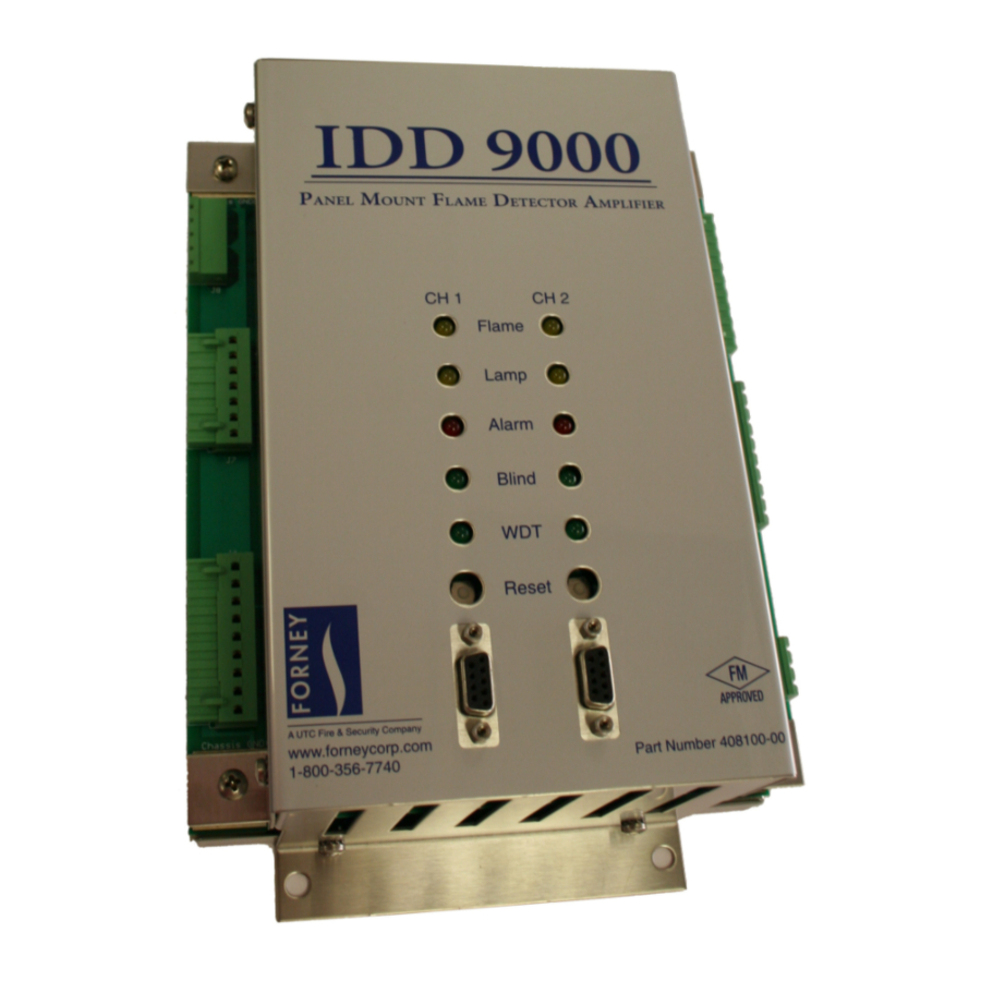
RM IDD9000
Forney RM IDD9000 Detector Amplifier Manuals
Manuals and User Guides for Forney RM IDD9000 Detector Amplifier. We have
1
Forney RM IDD9000 Detector Amplifier manual available for free PDF download: Manual
Forney RM IDD9000 Manual (36 pages)
Flame Amplifier
Brand:
Forney
| Category:
Amplifier
| Size: 8 MB
Table of Contents
Table of Contents
3
Section 1 General Description
5
Figure 1-1 RM IDD9000 Block Diagram
6
Specifications
7
Section 2 Installation
8
Recommended Test/Tuning Equipment and Instructions
8
Table 2-1 Tuning Equipment
8
Mounting Considerations
9
Electrical Connections
9
Figure 2-1 RM IDD9000 External Connectors
9
Figure 2-2 Detector Analog Signal Outputs J1 and J4
10
Outputs
10
RM IDD9000 Pin-Out Summary
10
Table 2-2 RM IDD9000 Pin-Out Summary for J1 and J4
10
Figure 2-3 Relay Connectors J2 and J5
11
Relays
11
Table 2-3 RM IDD9000 Pin-Out Summary for J2 and J5
11
Detectors
12
Figure 2-4 Control Inputs and Flame Scanners J6 and J3
12
Table 2-4 RM IDD9000 Pin-Out Summary for J6 an J3
12
Amplifier Upgrade Wiring Tables
13
Table 2-5 RM-IDD to RM IDD9000
13
Upgrading from an RM IDD
13
Table 2-6 RM-DR6101E to RM IDD9000
14
Upgrading from a RM DR6101E
14
Grounding the RM IDD9000
15
Figure 2-5 Grounding the RM IDD9000 to IDD-Ultra
16
Grounding New Applications
16
Retrofitting RM IDD9000 with an IDD-Ultra Detector
16
Retrofitting RM IDD9000 with IDD-II, IDD-IIU, or UV4 Detectors
16
LED Status Displays
17
Flame Detector Connections
17
Table 2-7 RM IDD9000 LED Indicators
17
Table 2-8 Control Inputs and Flame Detectors
17
Connecting IDD Detector Heads
18
Figure 2-6 IDD Detector Head Wiring Diagram
18
Connecting One IDD Detector Head to both IDD9000 Channels
19
Figure 2-7 IDD Detector Wired to both Channels 1 and 2 Wiring Diagram
19
Connecting UV-4 Detector Heads
20
Figure 2-8 UV-4 Detector Head Wiring Diagram
20
Connecting an IDD and a UV-4
21
Hardware Control Inputs
21
Blind Input - AC Powered J2 & J5, Relay Dry Contact J3 & J6
21
Sense B Input - AC Powered J2 & J5, Relay Dry Contact J3 & J6
22
Operating Profile Select Inputs - J3 & J6
22
Table 2-9 Profile Select Input Encoding
22
Operating Modes
23
Table 2-10 Stored Factory Defaults for Profile Modes
23
Configuring the Termiflex / Smartdisplay Terminal with 25-Pin Connector
24
Table 2-11 Termiflex / Smartdisplay ® Configuration Settings for IDD9000 Programming
24
Table 2-12 Termiflex/Smartdisplay ® Settings for DR6101E or RM-IDD Programming
25
Section 3 Amplifier Tuning
26
Mode
26
IDD Channel Tuning
26
Table 3-1 Keypad Commands
26
IDD Gain
27
IDD Frequency Ranges
27
Figure 3-2 Correct Gain Setting
27
Figure 3-1 Incorrect Gain Setting
27
IDD Pick-Up and Dropout Points
28
IDD Analog Output Low and High Points
29
Channel Tuning
30
Flame Failure Response Time Delay for Modes 1 and 2
31
Self-Check Cycle Time for Modes 1 and 2
31
Functions Unavailable While Tuning
32
Saving Configuration
32
Amplifier Shutdown/Failure
33
Analog Outputs
33
Section 4 Maintenance
34
Tuning
34
Troubleshooting
34
Storage and Handling Requirements
34
Recommended Spare Parts
35
Advertisement
Advertisement
Related Products
Forney 3832121
Forney 3832122
Forney 3832123
Forney 3832129
Forney IDD Series
Forney IDDX
Forney Categories
Welding System
Battery Charger
Remote Starter
Tools
Amplifier
More Forney Manuals
Login
Sign In
OR
Sign in with Facebook
Sign in with Google
Upload manual
Upload from disk
Upload from URL