Sign In
Upload
Manuals
Brands
FlyThisSim Manuals
Switch
TouchTrainer
FlyThisSim TouchTrainer Manuals
Manuals and User Guides for FlyThisSim TouchTrainer. We have
1
FlyThisSim TouchTrainer manual available for free PDF download: Setup Manual
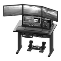
FlyThisSim TouchTrainer Setup Manual (71 pages)
Helicopter Flight Simulator
Brand:
FlyThisSim
| Category:
Switch
| Size: 6.92 MB
Table of Contents
Setup Guide
1
Table of Contents
2
List of Figures
3
Chapter 1: Assembling Hardware
6
Section 1: Unpacking
6
Base
7
Figure 1: Accessories, Cds, and Manual
8
Figure 2: USB Adapters
8
Section 2: Assembly
9
Touchtrainer® Table and Base
9
Figure 3: Leg Assembly for the Touchtrainer Table
9
Figure 4: Underside of Touchtrainer® Base as Packed
10
Figure 5: Topside of Touchtrainer® Base
11
Touchtrainer® Computer
12
Figure 6: Attaching Cables to the Back of the Computer
12
Figure 7: Plugging in Wi-Fi Adapter to Front of Computer for Commercial Edition
12
Figure 8: Connecting Visual Cables to the Back of the VISX Computer
13
Touchtrainer® MAIN Monitor
14
Figure 9: Connecting Cables to the Back of the 23" MAIN Display
14
Figure 10: Affixing the MAIN Monitor Bracket
14
Touchtrainer® AUX Monitor
15
Figure 11: Affixing the MAIN Monitor Bracket to the Base
15
Figure 12: Connecting Cables to the AUX Monitor
15
Touchtrainer® Joystick
16
Figure 13: Affixing the AUX Monitor to the Base
16
Figure 14: Joystick Location Overview
16
Figure 15: Placing the Joystick in the Slot
17
Figure 16: Affixing the Joystick in Place
17
Touchtrainer® Yoke and TPM Panel
18
Figure 17: Installing the Yoke (View from under the Table)
18
Figure 18: Installing the TPM
18
Touchtrainer® Throttle Lever
19
Figure 19: Nut Inserts for Linear Throttles
19
Figure 20: Twin Throttle Lever
20
Figure 21: Hardware Required for Changing from Single to Twin Throttle Lever
20
Figure 22: Views from the Rear of the Single and Twin Throttles
21
Figure 23: Connecting the Throttle USB Cable
21
Figure 24: Pushing the Throttle Cable through the Notch in Touchtrainer® Base
21
Touchtrainer® Rudder Pedals
22
Figure 25: Adjusting the Tension on the Rudder Pedals
22
Touchtrainer® VISX Monitors
23
Figure 26: Disassembled VISX System
23
Figure 27: Bolting the Left Cross-Member to the Central Member
23
Figure 28: Assembled Cross Members (Viewing from the Back)
23
Figure 29: Attaching the Cross Members to the Left Upright
24
Figure 30: Attaching the Assembly to the Right Upright
24
Figure 31: Backside of a Bolted VISX Monitor
24
Figure 32: Attaching the VISX Monitors
24
Figure 33: Plugging into the VISX Monitors
25
Figure 34: Placing the VISX System on the Table
25
Figure 35: Bolting the Uprights to the Bases
25
Figure 36: Visx Power Plug Located Behind the Center Monitor on the Underside of the Junction Box
26
Figure 37: Touchtrainer Power Plug Located at the Rear of the Base of the Left Visx Upright
26
Chapter 2: System Startup
27
Figure 38: Touchtrainer® Supervisor Startup Screen
27
Airplane Start-Up Procedures: before You Begin
28
Cirrus Avidyne and Analog Start-Up Procedure
29
Figure 39: Cirrus Avidyne Panel with no Power
29
Figure 40: Cirrus Avidyne Panel after Engine Start
29
Figure 41: Cirrus Avidyne Panel Ready for Takeoff
30
Cirrus Perspective Start-Up Procedure
31
Figure 42: Cirrus Perspective Panel with no Power
31
Figure 43: Cirrus Perspective Panel after Engine Start
31
Figure 44: Cirrus Perspective Panel with Avionics Activated
32
Figure 45: Cirrus Perspective Panel with Flight Plan Display
32
Figure 46: Cirrus Perspective Panel Ready for Takeoff
32
Steam Gauge (Analog) Start-Up Procedure
33
Figure 47: Cessna Analog with no Power
33
Figure 48: Cessna Analog after Engine Start
34
Garmin G1000 Start-Up Procedure
35
Figure 49: Cessna Garmin G100 with no Power
35
Figure 50: Cessna Garmin G1000 after Essential Bus Powered on
35
Figure 51: Cessna Garmin G1000 after Avionics Bus Powered on
36
Figure 52: Cessna Garmin G1000 Ready for Take-Off
36
Diamond Analog Startup Procedure
37
Figure 53: Diamond Analog Panel with no Power
37
Figure 54: Diamond Analog Panel Aftegns-430 Start
37
Figure 55: Diamond Analog Panel Ready for Takeoff
38
Diamond G1000 Startup Procedure
39
Figure 56: Diamond G1000 Panel with no Power
39
Figure 57: Diamond G1000 Panel after MFD Bootup
39
Figure 58: Diamond G1000 Panel after Engine Start
40
Figure 59: Diamond G1000 Panel Ready for Takeoff
40
Beech Analog Startup Procedure
41
Beech G1000 Startup Procedure
41
Figure 60: Bonanza Analog after Engine Start
41
Piper Analog Startup Procedure
42
Figure 61: Bonzana G1000 after Engine Start
42
Piper Avidyne Startup Procedure
43
Figure 62: Piper Arrow after Engine Start
43
Shutdown Procedure (All Panels)
44
Chapter 3: Standard Operating Procedures
45
Control Layout
45
Figure 63: Yoke Controls
45
Figure 64: Joystick Controls
45
Selecting an Aircraft
46
Figure 65: Simavio Command Buttons
46
Figure 66: Aircraft Selection Folders
46
Instructors Operation Station (I.O.S.): Setting Location, Fuel, and Weather
47
Figure 67: IOS Screen
47
Setting Time and Weather
48
Aircraft Failures
48
Figure 68: Weather and Time
48
Figure 69: Aircraft Failures
48
Loading a Scenario (NEW!!!)
49
Logging Time as an FAA Approved Basic Aviation Training Device
50
Chapter 4: Other Information
50
Configuring X-Plane Settings
50
Changing Graphics Settings
50
Configuring Buttons and Switches
51
Fetching and Installing Nav Data Updates
51
Figure 70: Nav Data Icon on the Desktop
51
Figure 71: Popup Downloads Window
51
Upgrading Simavio
52
Using Teamviewer
52
Figure 72: FTS Version Check Utility
52
Figure 73: Teamviewer Icon in the System Tray
52
Figure 74: Teamviewer Options Window
53
Computer Specifications
54
Product Warranties and Online Manuals
54
Computer Specifications for FTS RED
55
Product Warranties and Online Manuals
55
Chapter 5: Troubleshooting
56
Figure 75: Options Menu
56
Figure 76: Configuring the Surround Displays Options
56
Figure 77: Locking the Taskbar
57
Figure 78: Configure Surround Menu
57
Figure 79: Configure Display for Surround Menu
57
Figure 80: Connect Displays as Shown
58
Figure 81: Apply Configurations
58
Figure 82: Bezel Correction Selection
59
Figure 83: Bezel Width Adjustment Menu
59
Figure 84: Change Resolution Menu
60
Figure 85: Setting up Multiple Displays - Arranging the Main Touch Monitor
61
Figure 86: Setting up Multiple Displays - Arranging the Aux Monitor
62
Figure 87: Screen Resolution Window
63
Figure 88: Egalaxtouch Configure Utility
64
Figure 89: Main Display Monitor Mapping. Press the Space Bar on this Screen
64
Figure 90: Aux Display Monitor Mapping. Tap the Screen to Map this Display
64
Figure 91: the "Waiting for Connection" Screen
66
Chapter 6: Documentation
68
FAA Approval Copy
68
Certificate of Title
71
Figure 92: Certificate of Title Document Format
71
Advertisement
Advertisement
Related Products
FlyThisSim Categories
Switch
More FlyThisSim Manuals
Login
Sign In
OR
Sign in with Facebook
Sign in with Google
Upload manual
Upload from disk
Upload from URL