Sign In
Upload
Manuals
Brands
Fluke Manuals
Multimeter
8505A
Fluke 8505A Manuals
Manuals and User Guides for Fluke 8505A. We have
2
Fluke 8505A manuals available for free PDF download: Instruction Manual
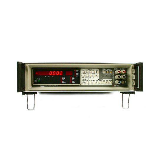
Fluke 8505A Instruction Manual (316 pages)
Brand:
Fluke
| Category:
Multimeter
| Size: 8.66 MB
Table of Contents
Operator Safety Information
3
Table of Contents
5
List of Tables
9
List of Illustrations
11
8505A Digital Multimeter View
12
Introduction & Specifications
13
Modular Construction
13
Description
13
Options
14
Accessories
14
General Specifications
14
DC Voltage
15
Input Characteristics
15
Accuracy
15
Operating Characteristics
16
DC Ratio
17
External Trigger Input
18
Scan Advance Output
18
Dimension Drawing
18
Operating Instructions
19
Shipping Information
19
Installation
19
Operating Notes
19
Controls, Indicators, and Connectors
20
Required Hardware
22
Power-Up Configuration
23
Display
23
Measurement Reading
23
Default Configurations
23
Overrange Indication
24
Warning Indication
24
Interactive Programming Information
24
Measurement Ranges
24
Error Codes
25
Momentary Error Conditions
25
Latching Error Conditions
25
Front Panel Push Buttons
26
Programming Hierarchy
33
Measurement Parameters
34
Mathematic Operations
35
Special Operations
36
Measurement Terminals and Controls
37
Volts Input/Ohms Sense (HI and LO) Terminals
37
Guarding Connections
37
Amps Input/Ohms Source (HI and LO) Terminals
37
Ohms Selector
38
Function
38
Sampling
38
Triggering
38
Measurement Connections
39
Range
40
V DC and Ohms Zero
40
Resolution
40
Scaling
41
External Reference
41
Offset
41
Peak
41
Limits
42
Remote Control
42
Calibration Mode
42
Scan Advance
43
Systems Use
43
Operation
43
Measurement Instructions
43
Applications
44
Storing a Displayed Value
44
Storing a Numeric Entry
44
Recalling
46
Remote Programming Commands
47
Programming Instructions
48
Initialization
48
Program Sequence
49
Immediate Characters
50
Reset
50
Halt
50
Go to Local-Lock out Remote
50
High Speed Reading Mode
51
Voltage and Current Reading in "I"
52
Ohms Readings in "I"
52
8/16 Bit Toggle
52
Termination Characters
53
Clear and Execute the Command String
53
Execute the Command String and Trigger
53
Execute, Trigger, and Interrupt When Ready
53
Command Characters
54
Function Command Characters
54
Range Command Characters
55
Modifier Command Characters
56
Samples Per Reading Command Characters
56
Filter Command Characters
57
Trigger Command Characters
57
Offset Command Characters
58
External Reference and Scaling Command Characters
58
External Reference On, Scaling off
58
External Reference Off, Scaling off & on
59
Limits and Peaks Command Characters
59
Limits Testing on
59
Save Highest and Lowest Values (Peaks On)
59
Control Command Characters
60
Output Format
60
The Binary Output Format
60
ASCII Data Output Format
61
Display Control
61
Local Lockout Control
61
Echo Command Characters (Used with Bit Serial Option-06 Only)
61
Line Feed Control Command Characters
62
Calibration Constant
62
External Trigger Delay Command Characters (-08A with 8502A Only)
63
Memory Command Characters
64
Store
64
Recall
65
Range Codes
66
Sample Codes
66
Function Codes
66
Programming Instructions (8505A, 8506A)
68
High Speed Mode
68
Averaging Command Characters
73
Binary Output Format
73
ASCII Output Format
74
Recall DC Zero (G0)
76
Recall Status (G1)
76
Additional Recall Commands
78
Theory of Operation
81
Block Diagram Description
81
Bus Structure
81
8505A Block Diagram
81
Analog Signal Flow
82
Controller
82
Background Software Process
83
Front Panel
83
Foreground Software Process
84
Controller Block Diagram
85
Active Filter
86
DC Signal Conditioner Block Diagram
86
Active Filter Block Diagram
86
Fast R2 A/D Converter
87
Front/Rear Switch Assembly
87
R2 A/D Converter Block Diagram
87
Circuit Analysis
88
Address and Data Buses
88
Mnemonics
88
Timing Circuits
89
Status Latch
89
Wait Logic
89
Interrupts
90
ACK Logic
90
Interrupt Generation Logic
91
DC Signal Conditioner
92
Filter/External Reference
92
Analog
96
Digital
96
Fast R2 A/D Converter (Analog)
97
Static Awareness
99
Maintenance
101
Service Information
101
Line Voltage Selection
101
Test Equipment
102
As Required by Installed Options
102
Power Supply Settings
103
Fuse Replacement
104
Module Installation and Removal
104
Module Disassembly and Reassembly
104
Calibration Memory Replacement
104
Front Panel PCB Removal
105
Power Supply Removal
105
Power Supply Interconnect PCB Removal
105
Removal and Replacement
105
Motherboard PCB Removal
106
Cleaning Instructions
106
Performance Test
106
Low Range DC Voltage Tests
106
Connections for Low Range DC Voltage Tests
107
High Range DC Voltage Tests
107
Connections for High Range DC Voltage Tests
107
Autoranging
108
Autoranging Test
108
DC External Reference Test
108
Calibration Adjustments
109
Power Supply
109
Initial Procedure
109
Checks and Adjustments
109
Power Supply Verifications
110
DC Signal Conditioner Adjustments
110
A/D Converter Calibration Procedures
110
DC Calibration Procedure
110
A/D Zero Adjustment
111
Control Setting
111
A/D Ladder Adjustments
111
Linearity Verification
111
Linearity Checks
112
Range Adjustments
112
Troubleshooting
113
Power Supply Troubleshooting
114
Guarded Supply
114
Unguarded Supply
114
Faulty Module Isolation
115
Controller Troubleshooting
120
Front Panel Troubleshooting
120
DC Signal Conditioner Troubleshooting
121
Address and Data Field
121
Active Filter Troubleshooting
122
Adjustment of R14
122
Selection of R15 or R16
122
R2 A/D Converter Troubleshooting
123
Digital Board
123
Analog Board
123
Troubleshooting Notes
124
Non-Recurring Adjustments
124
List of Replaceable Parts
125
How to Obtain Parts
126
Manual Status Information
126
Technical Service Centers
126
8505A Final Assembly
128
Front Panel Display PCB Assembly
131
Motherboard PCB Assembly
133
Isolator PCB Assembly
135
Power Supply PCB Assembly
137
Power Supply Interconnect PCB Assembly
140
Controller PCB Assembly
141
Front/Rear Switch PCB Assembly
143
DC Signal Conditioner PCB Assembly
145
Active Filter PCB Assembly
148
Fast R2 A/D Converter Assembly
150
Fast R2 A/D Analog PCB Assembly
151
A/D Analog PCB Assembly
153
Fast R2 A/D Digital Assembly
154
Fast R2 A/D Digital PCB Assembly
155
Federal Supply Codes for Manufacturers
156
Service Centers
158
Option & Accessory Information
161
Rack Ear Mounting Assembly
163
High Voltage Probe (80K-6, 80K-40, 83RF, 85RF)
163
Rack Ear Mounting Installation
163
AC/DC Converter (Averaging)
165
AC/DC Converter (Averaging) Specifications
166
Calibration Chart
168
Parts List
169
AC Converter Isolation
169
Symptom Analysis
170
AC/DC (Avg) PCB Assembly
171
AC/DC Converter (Averaging) PCB Assembly
175
Ohms Converter
177
Guarding
177
Ohms Converter Specifications
178
Temperature Coefficient
179
Maximum Lead Resistance
179
Open Circuit Voltage
179
Ohms Measurement Connections and Guarding
180
Calibration
181
Ohms Converter Simplified Schematic
182
Calibration Tests
183
Timing
184
Failure Isolation
185
Voltage Measurements
186
Range Switch Closures
186
Address and Data Coding
187
Ohms Converter PCB Assembly
188
Current Shunts
193
Current Shunts Specifications
194
Current Shunt Configurations and Range Information
197
Current Shunts Isolation
199
Current Shunts Assembly
201
IEEE-488 Interface
207
IEEE-488 Standard Cables
208
Rear Panel Access
208
Allowable Listen and Talk Addresses
208
Operating Features
209
Interface Control
209
Status Request Responses
209
Data Lines
209
Interface Messages
211
Resets
211
Control Register
211
Status Register
211
Message Decoder
212
Mode Register
212
Instrument Interrupts
212
IEEE 488-1975 Interface PCB Assembly
214
IEEE 488-1975 Piggy Back PCB Assembly
217
IEEE 488-1975 Interface Schematic
219
Piggy Back Schematic
220
Bit Serial Interface
221
Mode Selection
223
Baud Rate Selection
223
Jumper Arrangements
223
Interrupt
223
Bit Serial Interface Troubleshooting
225
Bit Serial Asynchronous Interface PCB Assembly
226
Parallel Interface
231
Personality Card Pin Definition
231
Personality Card Location
232
Operating Directions
233
Block Diagram Analysis
233
Addresses
235
Data Inputs
235
Data Outputs
235
Detailed Input Processes Description
236
Parallel Interface Connections
236
Detailed Output Processes Description
237
Interface Input Control Signal Timing Diagram
237
Input Timing Parameters
238
Output Timing Parameters
238
Interface Output Control Signal Timing Diagram
239
Parallel Interface PCB Assembly
241
-07A Personality Card PCB Assembly
245
-07B Personality Card PCB Assembly
246
-07D Personality Card PCB Assembly
247
-07H Personality Card PCB Assembly
248
Isolator -08A (External Trigger)
249
Input
249
Trigger Processing Time
249
Local Operation
249
Remote Operation
250
Remote Commands
250
Trigger Polarity Connections
250
Isolator Block Diagram
251
Isolator Troubleshooting
252
Option-09A AC/DC Converter (RMS)
257
AC/DC Converter (RMS) Specifications
258
AC/DC Converter (RMS)
259
Circuit Description
260
Range Amplifier
260
Balance Amplifier
260
Computation
260
Preliminary Calibration
264
High Voltage, Low Frequency Coarse Adjust
265
RMS Converter PCB Assembly
266
Software Calibration
273
Software Calibration Points
274
Detailed Description/Operation
274
Software Cal Mode Switch
274
Zero Corrections
274
Store Operations
275
Recall Operations
275
Gain Corrections
275
Gain Correction Parameters
276
DC Voltage Calibration
277
Calibration Date and Identification Number
277
Clear Operations
278
Error Conditions
278
Local Calibration
279
Permanent Zeros
279
Reference Sources
280
AC Volts
281
Ohms
282
Permanent Zeroes
282
DC Current
283
Remote Calibration
283
Schematic Diagrams
287
List of Mnemonics
289
Isolator PCB Assembly
296
Power Supply Interconnect PCB Assembly
301
Controller Assembly
303
Fast R2 A/D Converter Digital PCB Assembly
314
Advertisement
Fluke 8505A Instruction Manual (70 pages)
Brand:
Fluke
| Category:
Multimeter
| Size: 2.31 MB
Table of Contents
Specifications
3
General Specifications
4
Operating Mode
5
Source Impedance
7
Normal Mode
7
Common Mode
7
External Trigger
8
Operating Notes
9
Error Codes
14
Measured Value
31
Operation
33
Remote Code
38
Memory, Control
44
High Speed
45
Range Command
45
Offset Command
48
Control Command
50
High Speed Mode
58
Standard Mode
61
Calibration Mode
62
Output Format
64
Advertisement
Related Products
Fluke 8508A
Fluke 8520A
Fluke 85
Fluke 8506A
Fluke 8502A
Fluke 8588A
Fluke 8558A
Fluke 87 Series IV
Fluke 8012A
Fluke 87V MAX
Fluke Categories
Measuring Instruments
Test Equipment
Multimeter
Thermometer
Laboratory Equipment
More Fluke Manuals
Login
Sign In
OR
Sign in with Facebook
Sign in with Google
Upload manual
Upload from disk
Upload from URL