Sign In
Upload
Manuals
Brands
Flowserve Manuals
Controller
MX
Flowserve MX Manuals
Manuals and User Guides for Flowserve MX. We have
1
Flowserve MX manual available for free PDF download: Installation, Operation, Maitenance Manual
Flowserve MX Installation, Operation, Maitenance Manual (112 pages)
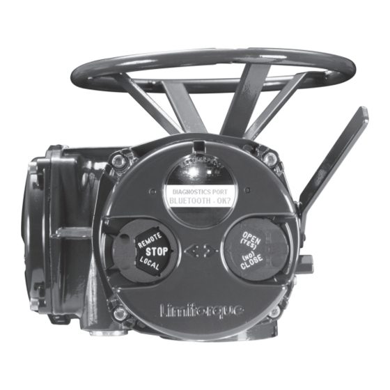
Electronic Actuator
Brand:
Flowserve
| Category:
Controller
| Size: 8 MB
Table of Contents
Table of Contents
2
1 Important Notes
8
Figure 1.1 - MX-05 Actuator
8
Limitorque ® MX Electronic Actuator FCD LMENIM2306-09-AQ
8
2 Quick Start
10
Calibrate - Position Limits
11
Entering the Setup Mode
11
Electrical Operation Feature
11
Handwheel Operation Feature
12
Figure 2.1 - Electrical Operation
12
Figure 2.2 - Handwheel Operation
13
DDC/Modbus Option
14
Check the Settings
14
3 Installation and Operation
15
Preparing the Stem Nut
15
Type "B" Bases: Torque-Only Applications
15
Figure 3.1 - B4 Base
15
Figure 3.2 - B4E Base
16
Figure 3.3 - Exploded View of B4/B4E Base (MX-05 Shown)
16
Type "A" Bases: Thrust-Only Applications
17
Figure 3.4 - B1 Base
17
Figure 3.5 - Exploded View of B1 Base
17
Figure 3.6 - A1 Base
17
Figure 3.7 - Exploded View of A1/A1E Base (MX-05/10/20/40 Only)
18
Table 3.1 - Hardware and Torque for Thrust Base Mounting
19
Figure 3.8 - Exploded View of Thrust Base (MX-85 Only)
20
Type "BL" Drive: Splined Drive Application
21
Mechanical Installation Onto Valve or Gearbox
21
Figure 3.9 - Exploded View of Thrust Base (MX-140/MX-150 Only)
21
Mounting (Type "B" Bases): Torque-Only
22
Removal (Type "B" Bases): Torque-Only
22
Mounting (Type "A" Bases): Thrust-Only
22
Removal (Type "A" Bases): Thrust-Only
22
Electrical Connections
23
Removing Terminal Cover
23
Terminal Compartment Documents
23
Sealing Cable/Conduit Entries
23
Recommended Terminal Connections
23
Figure 3.10 - Power Terminal Connector Size Limitations
24
Figure 3.11 - Terminal Block Rating; Power Terminals
24
Figure 3.12 - Control Terminal Connector Size Limitations
24
Termination of Cables
25
Cable Connections
25
Network Installations
25
Table 3.2 - Terminal Block Rating; Control Terminals
25
Table 3.3 - Required Ratings for External Wires
25
Figure 3.13 - View of Terminal Block
26
Figure 3.14 - Standard Wiring Diagram
26
Figure 3.15 - Removing Outer Plastic Jacket
27
Figure 3.16 - Separating Cable Parts
27
Figure 3.17 - Stripping Conductors and Applying Heat Shrink Tubing
28
Figure 3.18 - Ring Tongue Connectors
28
Table 3.4 - Loop Topology Connections
28
Foundation Fieldbus Installation
29
Table 3.5 - Foundation Fieldbus Connections
29
Network Wiring - Profibus DP/PA Installation
30
Network Wiring - Devicenet
30
Table 3.6 - Profibus Cable Specifications
30
Table 3.7 - Devicenet Cable Specifications
30
HART Installation
31
Replacing Terminal Cover
31
External Earth/Ground Connections
31
Terminal Block Shield Installation
31
Commissioning the Actuator
31
Figure 3.19 - Terminal Block Shield
31
Default Configuration Set
32
Figure 3.20 - User Network Connection for Loop Topology/Typical for All Two-Wire Network Protocols
32
Figure 3.21- External Earth/Ground Connection - Housing
32
Entering the Setup Mode
33
Table 3.8 - Default Configurations
33
View the Existing Settings
33
Figure 3.22 - View Settings
34
Setting Position Limits
34
Figure 3.23 - Position Setup - Electrical Operation
36
Operating the MX Actuator
37
Manual Operation
37
Electrical Operation
37
Local Control
37
Figure 3.24 - Declutch Lever Shows Direction of Engagement (MX-05 Shown)
37
Remote Control
38
Local Indication
38
Figure 3.25 - Control Panel
38
Table 3.9 - LED Indicators - Default Settings
38
4 Customizing the Actuator
39
Changing the Existing Settings
39
Figure 4.1 - Entering the Setup Mode
40
Figure 4.2 - Main Menu Selections
41
Figure 4.3 - Changing Settings
41
Password Entry
42
New Password
42
Figure 4.4 - Password Entry
42
Valve Setup
43
Close Direction
43
Close Seating
43
Open Seating
43
Figure 4.5 - New Password
43
Torque Switch Timer
44
Status
44
Torque Timer
44
Figure 4.6 - Torque Switch Timer
44
Torque Setup
45
Close Torque Valve or Open Torque Valve
45
Figure 4.7 - MX Nameplate
45
Figure 4.8 - Torque Setup
45
Position Setup
46
Set Position Limits for Electrical Operation
46
Set Position Limits for Manual Operation
46
Figure 4.9 - Electrical Operation
47
Figure 4.10 - Handwheel Operation
47
Modutronic Option
48
Status
48
Proportional Band
48
Fail Position
48
Deadband
48
Polarity (20 Ma)
48
Delay after Stop
49
Ma Signal Range
49
Set High Reference
49
Set Low Reference
49
Figure 4.11 - Modutronic Option
49
Modutronic LCD Display
50
DDC/Modbus Option
50
Status
50
Figure 4.12 - Modutronic Signals
50
Network Address
51
Protocol
51
Analog Scale
51
ESD Action
51
Figure 4.13 - DDC
51
Proportional Band
52
Deadband
52
Offset
52
Move to
52
Comm Loss Delay
52
Comm Loss Action
52
FF Option
52
Status
53
Terminate Bus
53
Analog Scale
53
ESD Action
53
OPEN/CLOSE Mode
53
Proportional Band
53
Deadband
53
Comm Loss Delay
54
Comm Loss Action
54
PB Option
54
Figure 4.14 - FF
54
Figure 4.15 - Profibus DP
55
PB DP Operation
55
Status
55
Comm Loss Action
56
Comm Loss Delay
56
Figure 4.16 - Profibus PA
56
DN Option
57
Status 57
57
Baud Rate
57
Network Address
57
Analog Scale
57
ESD Action
57
Proportional Band
58
Deadband
58
Comm Loss Delay
58
Comm Loss Action
58
Figure 4.17 - DN Option
58
HART Option
59
Status
59
Multi-Drop
59
Figure 4.18 - HART
59
Input Action
60
Fail Position
60
Polling Address
60
Save Settings
60
Change Prop/Deadband
60
ESD Action
60
Change Clock
61
Status and Alarm Contacts
61
Status and Alarm Contact Default Settings
61
Status Function
62
Contact
62
Figure 4.19 - Status and Alarm Contacts (Shown with Optional Boards Needed)
62
Valve Position
63
Two-Speed Timer (Optional)
63
Status
63
Start Position
63
Stop Position
63
Pulse Time - on
63
Pulse Time - off
64
Analog Output
64
Figure 4.20 - Two-Speed Timers
64
Figure 4.21 - Change Analog out
64
Figure 4.22 - Change Analog out Voltage - APT
65
Figure 4.23 - Change Analog out Current
65
Figure 4.24 - Change Analog out Voltage - ATT
66
Figure 4.25 - Change Analog out Current - ATT
66
APT Polarity Option
67
ATT Polarity Option
67
Remote Mode
68
Local Control
68
Figure 4.26 - Remote Mode
68
Figure 4.27 - Local Control
68
LED Customization
69
ESD (Emergency Shutdown) Overrides
69
ESD Override
69
Figure 4.28 - ESD Overrides
69
Inhibit
70
Local Command
70
Stop
70
Jammed Valve
70
Lost Phase
70
Overtorque
71
Motor Thermostat
71
Oil over Temperature
71
Two-Speed Timer
71
Network ESD
71
Torque Switch Timer
72
Inputs
72
Input Standard Remote Control
72
Status
73
Custom Input Mode #1 - Momentary ESD/PSESD (Optional)
73
Figure 4.29 - Custom Input Modes
75
Custom Input Mode #2 - Momentary ESD/CSE (Optional)
76
Custom Input Mode #3 - ESD Time Delay Relay
76
Custom Input Mode #4 - Multi-Position Mode (Optional)
77
Figure 4.30 - Inputs
77
Limigard Controls
78
SIL Mode - Standard SIL (Optional)
78
Figure 4.31 - Inputs
78
SIL Mode - Enhanced SIL (Optional)
79
Figure 4.32 - SIL Control (Standard)
79
Table 4.1 - Digital Input Terminals
80
Figure 4.33 - SIL Control (Enhanced)
81
Monitor Relay
82
Figure 4.34 - Monitor Relay Configuration
82
Diagnostic Reset
83
TAG Number
83
Figure 4.35 - Diagnostic Reset
83
LCD Contrast
84
Torque Boost
84
Figure 4.36 - TAG Number
84
Figure 4.37 - LCD Contrast
84
Motor Thermostat
85
Change Valve Data
85
Figure 4.38 - Torque Boost
85
Figure 4.39 - Motor Thermostat
85
Change Port
86
Figure 4.40 - Change Valve Data
86
Figure 4.41 - Change Port and Bluetooth Settings
86
5 Troubleshooting
87
View Diagnostics Routine
87
Troubleshooting Problems/Corrective Action
87
Actuator Fails to Operate
87
Jammed Valve Detected
88
Actuator Operates but Does Not Drive Valve
89
Valve Does Not Seat Correctly
89
Status Messages
89
Figure 5.1 - Initialize Routine
91
View Diagnostics
92
Figure 5.2, Single Phase Only Initialize Routine
92
View Hardware Status
93
Figure 5.3 - Diagnostic Overview
93
Figure 5.4 - View Hardware Status for Single Phase
93
View Motor Status
94
Figure 5.5 - View Three Phase ACV Hardware Status
94
Figure 5.6 - View Three Phase ACV Motor Status
94
Figure 5.7 View Single Phase Motor Status
94
View Power Supply
95
View Identification
95
Figure 5.8 - View Power Supply
95
Figure 5.9 - View Single Phase Power Supply
95
Figure 5.10 - View Identification
95
View Torque Profile
96
Figure 5.11 - View Single Phase Identification
96
Figure 5.12 - View Torque Profile
96
View Operation Log
97
Figure 5.13- View Operation Log
97
View DNET Status
98
Figure 5.14 - View DNET Status
98
6 Maintenance
100
Lubrication
100
Oil Capacities
100
Checking Oil Level
100
7 Regulatory Information
101
Specific Conditions of Use (Denoted by X after the Certificate Number) for Atex and Iecex Applications
104
Statement of Compliance with Applicable European Directives
104
MX Electronic Actuator FCD LMENIM2306-09-AQ - 08/17
105
Table 7.1 - EMC, EMI Standards
105
Single-Phase MX Full Load Amperage Values (FLA)
106
Figure 7.1 - Typical Three-Phase IEC Nameplate
107
Figure 7.2 - Typical Single Phase MX Iecex Nameplate
108
Figure 7.3 - Typical Three Phase MX ATEX Nameplate
109
Advertisement
Advertisement
Related Products
Flowserve Limitorque MX-40
Flowserve Limitorque MX-140
Flowserve Limitorque MX-150
Flowserve Limitorque MX-10
Flowserve Limitorque MX-05
Flowserve Limitorque MX-20
Flowserve Limitorque MX-85
Flowserve MXa/QXM Linear Base
Flowserve MPT 80
Flowserve SIHI dry Standard M100
Flowserve Categories
Control Unit
Controller
Water Pump
Valve Positioners
Racks & Stands
More Flowserve Manuals
Login
Sign In
OR
Sign in with Facebook
Sign in with Google
Upload manual
Upload from disk
Upload from URL