Sign In
Upload
Manuals
Brands
FLIR Manuals
Radar
Ranger R2
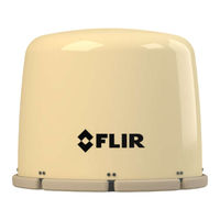
User Manuals: FLIR Ranger R2 Surveillance Radar
Manuals and User Guides for FLIR Ranger R2 Surveillance Radar. We have
2
FLIR Ranger R2 Surveillance Radar manuals available for free PDF download: Operator's Manual, Installation And Maintenance Manual
FLIR Ranger R2 Operator's Manual (81 pages)
Mid-Range Perimeter Surveillance Radar
Brand:
FLIR
| Category:
Radar
| Size: 4 MB
Table of Contents
Table of Contents
7
1 Introduction
11
1.1 Safety Issues
11
2 Psr System Operation
13
2.1 Radar Application Manager
13
Figure 1 - Radar Application Manager Main Window
13
Application Name
14
Application Parameters
14
Application Running Time
14
Application Status
14
Event Log Window
14
Image Name
14
2.2 Radar Console
15
Operator Login
15
Figure 2 - Login Operator Mode
15
Figure 3 - Radar Console Displaying Available Radars
15
Table 1 - Radar Console Functions Vs. Login Level
17
Figure 4 - Radar Lexicon
18
Table 2 - Radar Icons and Messages
20
Figure 5 - Radar Control
21
Figure 6 - Radar Information
21
Radar Mode Change (Applies Only to R3D and R5D Radars)
22
Figure 7 - Changing Range in Fastscan Mode
22
Figure 8 - Changing Range and Time-On-Target in Doppler Mode
23
Radar Mode Change (Applies Only to R4SS-X, R6SS-X and R8SS-X Radars)
24
Figure 9 - Changing Mode on a R6SS or R6SS-U
24
Figure 10 - Changing Range and Time-On-Target on a R4SS-X, R6SS-X or R8SS-X
24
Regular Scan Mode Change (Applies Only to R4SS-X, R6SS-X, R8SS-X and R20SS Radars)
25
Figure 11 - Pan/Tilt Positioner Enable Parameter
25
Figure 12 - Fixed Mode Configuration Parameters
26
Figure 13 - Continuous Mode Configuration Parameters
27
Figure 14 - Alternating Mode Configuration Parameters
28
Editing Zones
29
Figure 15 - Contact and Intrusion Zones
30
Figure 16 - Edit Menu
31
Figure 17 - Creating a Zone (Step 1 of 4)
32
Figure 18 - Creating a Zone (Step 2 of 4)
33
Figure 19 - Creating a Zone (Step 3 of 4)
34
Figure 20 - Creating a Zone (Step 4 of 4)
35
Figure 21 - Changing Segment Adding Order
36
Figure 22 - Edit Menu Commands
37
Figure 23 - Edit Menu Commands
37
Figure 24 - Zone Edition Context
38
Figure 25 - Modifying a Zone (Step 1 of 2)
39
Figure 26 - Modifying a Zone (Step 2 of 2)
40
Figure 27 - Edit Menu Commands
41
PPI Display
42
Figure 28 - View Menu Commands
42
Figure 29 - Cursor Position Indicator
43
Figure 30 - Radar PPI (Continuous)
44
Figure 31 - Radar PPI (Snapshot) Mode
45
Table 3 - PPI Commands
46
Figure 32 - Background Map
47
Figure 33 - PPI Color Palette
48
Figure 34 - Radar Location
48
Figure 35 - Range Rings
49
Figure 36 - View Menu Commands
50
Figure 37 - Intrusion Zones (Red Boundary)
51
Figure 38 - Contact Zones (Yellow Boundary)
52
Figure 39 - Intrusion Zones Coverage
53
Figure 40 - Contact Zones Coverage
54
Intruders and Targets
55
Figure 41 - Description of Intruder and Target Symbols
55
Figure 42 - Selected Intruder / Target Status Line Information
56
Figure 43 - Targets/Intruders List View
56
Figure 44 - Targets/Intruders Tree View
57
Figure 45 - Track Recovery Enable Parameter
58
Figure 46 - Tracks Being Coasted
59
Figure 47 - Track Being Recovered
59
Figure 48 - Radar Contacts
60
Recording Data
61
Figure 49 - Record Targets/Intruders Log Command
61
Figure 50 - Targets/Intruders Log File Example
61
Figure 51 - Record Radar Data Menu
62
Figure 52 - Record Radar Data Duration
62
Figure 53 - Radar Standby and Transmit Commands
63
Radar Operations
64
Figure 54 - Logs Window
65
Figure 55 - Setup Menu
65
Figure 56 - Logs File Example
65
2.2.10 Radar Configuration Parameters
66
Table 4 - Configuration Parameters Groups
66
Table 5 - Radar Configuration Parameters Access Vs. Login Level
68
Table 6 - Configuration Parameter Descriptions
71
Figure 57 - Parameters Window
72
Figure 58 - Changing Parameter Values
73
Figure 59 - Programming Unit Parameters
74
Figure 60 - Current Parameter Group Commands
75
Figure 61 - Default Parameter Group Commands
76
Figure 62 - Exporting Radar Parameters (Step 2)
77
Figure 63 - Exporting Radar Parameters (Step 3)
78
Figure 64 - Exporting Radar Parameters (Steps 4 and 5)
78
Figure 65 - Exporting Radar Parameters (Step 6)
79
3 Troubleshooting
80
Advertisement
FLIR Ranger R2 Installation And Maintenance Manual (53 pages)
Brand:
FLIR
| Category:
Radar
| Size: 6 MB
Table of Contents
Table of Contents
7
1 Introduction
10
Equipment Features and Specifications
10
Table 1 - R1, R2, R3, R3D, R5 and R5D Radar Assembly Specifications
10
Safety Issues
12
UNPACKING the R1, R2, R3, R3D, R5 and R5D RADAR ASSEMBLY
12
2 Hardware System Description
13
Hardware Component Description
13
Physical System Overview
13
Figure 1 - R1, R2, R3, R3D, R5 and R5D Radar Systems Physical Overview
13
Figure 2 - Left: R1, R2, R3 Center: R3D Right: R5, R5D
14
3 Planning System Installation
15
Radar Assembly Installation
15
Figure 3 - Optimizing Radar Location (Aerial View)
16
Table 2 - Installation Considerations
17
Figure 4 - Optimizing Grazing Angle
18
Figure 5 - Radar Installation on Even Terrain - Incorrect Height and Incorrect Tilt Angle
18
Figure 6 - Radar Installation on Even Terrain - Incorrect Height and Correct Tilt Angle (Only Applicable to Fastscan Mode)
19
Figure 7 - Radar Installation on Even Terrain - Correct Height and Tilt Angle
19
Figure 8 - Radar Installation Near Rising Terrain - Sub-Optimal Radar Position and Tilt Angle
19
Figure 9 - Radar Installation on Even Terrain - Incorrect Height
20
Figure 10 - Radar Installation Near Rising Terrain - Correct Radar Position and Tilt Angle
20
Figure 11 - Radar Installation on Hill Top - Incorrect Tilt Angle
20
Figure 12 - Radar Installation on Hill Top - Correct Tilt Angle (Only Applicable to Doppler Mode)
21
Figure 13 - Radar Installation Near Hill - Shadowed Zone
21
Figure 14 - Radar Installation Near Hill - no Shadowed Zone
21
Power Distribution Network
23
4 Hardware Installation
23
Radar Assembly Installation
23
Figure 15 - Top Left - R1, R2 and R3; Top Right - R3D; Bottom - R5 and R5D: Outline
24
Figure 16 - Left - R1, R2, R3 and R3D; Right - R5 and R5D: Mounting and Connector Location
25
Figure 17 - Regular Mounting Plate Outline
25
Figure 18 - Radar Mounting
27
Figure 19 - Preventing Water Accumulation at Radar Base
28
Figure 20 - Radar Spacer
28
Antenna Tilt Adjustment
29
Figure 21 - Overhanging Mounting Plate
29
Table 3 - R1, R2 and R3 Minimum/Maximum Detection Range for Low Crawler, Walker and Car
30
Table 4 - R5 Minimum/Maximum Detection Range for Low Crawler, Walker and Car
31
Table 5 - R3D Minimum/Maximum Detection Range for Low Crawler, Walker and Car; LONG Time-On-Target
32
Table 6 - R5D Minimum/Maximum Detection Range for Low Crawler, Walker and Car; LONG Time-On-Target
33
Radar Power Distribution Network Installation
35
Figure 22 - Power/Data Connector Pin out
35
Network Infrastructure Installation
36
Table 7 - Power / Data Connector Pin Assignment - R1, R2, R3, R3D, R5 and R5D
36
5 Radar Transmission Configuration
37
Configuring the Radar Target Azimuth Update
37
Figure 23 - Good and Bad Choices for Radar Target Azimuth Update
37
Configuring the Chirp Slots
38
Figure 24 - Configuring the Target Azimuth Update
38
Table 8 - R1, R2, R3, R3D, R5 and R5D Radar Assemblies Synchronization Method
39
Figure 25 - Reusing Chirp Slots
40
Table 9 - Number of Radars for Multiple Radar Modes R1, R2, R3 and R3D
41
Table 10 - Number of Radars for Multiple Radar Modes R5 and R5D
41
Figure 26 - Configuring Chirp Slots
42
Configuring Transmission Sectors
43
Table 11 - Transmit Sectors
43
Figure 27 - Configuring the Radar Assembly Transmission Sectors
44
6 Troubleshooting
45
Table 12 - Radar Failure Category Definition
45
Table 13 - Radar Sub-Assembly Definition
46
7 Maintenance
47
Visual Inspection
47
Recommended Maintenance Schedule
47
Table 14 - Recommended Maintenance Schedule
47
Cleaning the Unit
48
External Mechanical Inspection
48
Removing the Radome
48
Figure 28 - Radome Screws Location
48
Replacing the Radome
49
Internal Mechanical Inspection
49
Figure 29 - Steps 3 & 4: Check Spur Gears
50
Figure 30 - Check Mechanical Components (R5, R5D Shown)
50
Replacing the Membrane Gore Vent
51
Figure 31 - Verify for Loose Payload (R5, R5D Shown)
51
Figure 32 - Gore Membrane Vents
51
Advertisement
Related Products
FLIR Ranger R20SS
FLIR Elara R-290
FLIR Ranger R Series
FLIR Ranger R1
FLIR Ranger R3
FLIR Ranger R5D
FLIR Ranger R5
FLIR Ranger R3D
FLIR Ranger R8SS-X
FLIR Ranger R6SS-X
FLIR Categories
Thermal cameras
Security Camera
Measuring Instruments
Digital Camera
Thermographic Cameras
More FLIR Manuals
Login
Sign In
OR
Sign in with Facebook
Sign in with Google
Upload manual
Upload from disk
Upload from URL