Sign In
Upload
Manuals
Brands
Flexball Manuals
Marine Equipment
5000 Series
Flexball 5000 Series Manuals
Manuals and User Guides for Flexball 5000 Series. We have
1
Flexball 5000 Series manual available for free PDF download: Operating Manual
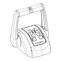
Flexball 5000 Series Operating Manual (120 pages)
Electronic command system for marine engines
Brand:
Flexball
| Category:
Marine Equipment
| Size: 7 MB
Table of Contents
Warranty
2
Table of Contents
3
Introduction
6
How to Start
6
System Configuration and Installer Remarks
6
General Installation Features
7
Description of the System and Its Parts
7
Maximum Extension of the System
7
System Performance
7
Pilot Instructions
8
Control Keypad
9
Acquisition of the Command
11
Engine Warm-Up
11
Single Lever Mode
12
Fast Start-Up Mode
12
Emergency Lever
12
Command Station
13
Dimensions
13
Command Station Series 4000
13
Command Station Series 4200
14
Command Station Series 4500
14
Command Station Series 5000
15
Removal of the Protective Cover (When Present)
15
Programming of the Command Station
16
For Command Stations before Serial Number 18500
16
For Command Stations after Serial Number 18500
17
4500 And 5000 Two-Engine Stations: How to Assign the Single Lever Function to the Operating Lever (after Serial Number 18500)
17
Command Station Label
18
Trolling Option
18
Trim/Flap Option
19
Classification of Indoor and Outdoor Installation
21
Advices about the Mounting and Preservation of the Command Station
23
Actuator
24
Drawing of Actuators with Mechanical Interface
24
Drawing of Full Electronic Actuator
25
How to Mount the Actuator
25
Electronic Actuator Boards
26
Actuator 4.0 (4600 Series)
26
Actuator 3.1
27
RB 1.X for TRIM-FLAP and Neutral Relays
28
Psbv2.0 for Electronic Gearboxes
29
VANCONV-PCB: CAN Bus, PWM or 4-20Ma Interface Towards Engine
30
Isov2.1 PCB
31
Actuator Labels and Codes
32
Accessories and Options
33
Canbus Cable
34
Canbus Data Transmission Cable
34
Canbus Extension Cable
34
Cables for Electronic Engine
34
Cable for 1 Electronic Enginewith 1 Channel: Voltage, PWM, 4-20 Ma
34
Cables for 1 Electronic Engine (V) with 2 Channels (Standard and Ratiometric)
35
Nanni Diesel - Throttle Cable for Toyota Motor Version
36
Nanni Diesel - Cable for the Inverter (Hybrid Propulsion)
36
Nanni Diesel - Command Cable for Throttle and Inverter
37
Nanni Diesel - y Cable for Electronic Toyota Engine(V) + Inverter (V)
37
Nanni Diesel - y Cable for VM Electronic Engine (V) + Inverter (V)
38
FPT - Throttle Canbus Command Cable
38
Cable Actuator - Canbus Engine with Free Wire
39
FNM - Throttle Cable
39
Hyundai - Throttle Cable
40
Steyr -Throttle Cable, Type a (Ch2 = IVS Signal)
40
Steyr -Throttle Cable, Type B, for Engines Series "SE
41
Cable Actuator - Gearbox Solenoid Driven
42
Nanni Diesel - Cable for Gearbox Solenoid Driven
42
FPT - Cable for Gearbox Solenoid Driven
42
Cable Actuator - Gearbox Solenoid Driven + Neutral Relay Signal
42
Nanni Diesel - Cable for Gearbox Solenoid Drive + Neutral Signal
44
Cable Actuator - Trim/Flap
44
Nanni Diesel - Cable for the Trim/Flap Command
44
Cable Actuator -Mercruiser® Trim Pump
45
T-Splitter
46
Power Supply Connector
46
Configuration of the Canbus Network
47
Installation with 2 Mechanical Actuators - Solution a
48
Installation with 2 Mechanical Actuators - Solution B
49
Installation with 2 Mechanical Actuators - Solution C
50
Installation with 1 Actuator - Solution D
51
Installation with 1 Actuator - Solution E
52
Configuration: End of Line Termination Resistor and Address Setting of Command Stations and Actuators
53
Configuration of the Command Station
53
Configuration of the Actuator
55
Configuration with more than 3 Command Stations
57
4600 Series Switch Settings
58
Electrical Installation
59
Wiring from the Battery to the Actuator (Input Cables)
59
Supply Connector
59
The Ignition Key Switch
60
Electrical Installation of Systems with 1 Engine, 1 Actuator and 1 Ignition Key
60
Electrical Installation of Systems with 2 Engines, 1 Actuator and 2Ignition Keys
61
Electrical Installation Systems with 1 Engine, 1 Actuator and 2 Ignition Keys
61
Electrical Installation of Systems with 2 Engines, 2 Actuators and 2 Ignition Keys
62
Electrical Installation of Systems with 2 Engines, 2 Actuators and 4 Ignition Keys
63
Dimensional Criteria of the Power Supply Cables
63
Wiring from the Actuator to Command Stations, Engines, Gearboxes, Trim/Flaps, Etc (Output Cables)
64
Actuator with Mechanical Interface Without Neutral Relay
64
Actuator with Mechanical Interface and Neutral Relay
65
Actuator with Full Electronic Interface
66
Actuator with Full Electronic Interface and Neutral Relay
66
Wiring Scheme to Gearbox in Case of Actuator Without Neutral Relay
67
Wiring Scheme to Gearbox in Case of Actuator with Neutral Relay
67
Wiring Scheme from Actuator to Trim/Flap with External Supply
68
Wiring Scheme from Actuator to Trim/Flap with Internal Supply
68
Programming of the Actuator, General Guidelines
69
Programming Keypad
69
Display, Menus and Parameters
70
Actuator Parameters
71
Installation of the Push-Pull Cable and Stroke's Programming on the Actuator
72
Push-Pull Cables Choice
72
Connection Kit
72
Standard Push-Pull Cable (E2, E3, Volvo®, C0, C3, C33
72
Mercruiser® Stern Drive Push-Pull Cable
72
Johnson® Push-Pull Cable
73
Mounting of the Push-Pull Cables between Engine and Actuator
74
Connection of the Push-Pull Cable to the Engine
74
Connection of the Push-Pull Cable to the Actuator
74
Mounting of the Push-Pull Cable between Gearbox and Actuator
77
Connection of the Push-Pull Cable to the Gearbox Side
77
Connection of the Push-Pull Cableto the Actuator
77
Programming of the Strokes on Actuator with Mechanical Interface to Engine and Gearbox
80
Programming of the Push-Pull Cable Strokes
81
Sea Trials
83
Specific Parameters
84
Programming of Actuators for Installations with Electronic Engine and Mechanical Gearbox
85
Programming of the Gearbox Strokes
86
Sea Trials
88
Specific Parameters
90
Parameters to Configure the Voltage Output Signal for Electronic Engines
90
Parameters to Configure the Voltage Output Signals
91
Programming of Actuators for Mechanical Engines and Electronic Gearbox
92
Mounting of the Engine the Push-Pull Cable and Programming of Throttle Mechanical Strokes
92
Programming of the Push-Pull Cable Strokes
92
Electrical Cabling of the Gearbox
92
Specific Parameters
92
Electrical Wiring
93
Programming of Actuators with Electronic Engine and Electronic Gearbox
93
Specific Parameters
93
Programming of Actuators with Electronic CANBUS Engine and Mechanical Gearbox
94
Installation of the Push-Pull Cable and Programming of the Cable Stroke
94
Specific Parameters
94
Canbus Protocol
94
Setting of the Canbus Parameters
95
Technical Data of the Canbus Interface Card
96
Wiring of the Outgoing Actuator Cables
96
Connection to FPT Engines through Canbus Interface
96
Programming of Actuators with Electronic CANBUS Engine and Electronic Gearbox
99
Canbus Engine Parameters
99
Electronic Gearbox Parameters
99
Wiring of the Actuator Outgoing Cables
99
System Configuration in Case of Options
99
Commissioning of Actuators for Installations with Trim or Flap Command Option
99
Commissioning of Actuators for Installations with Trolling Option
99
Commissioning of the Actuators with Neutral Relay Option
100
Programming of the Actuators with Hybrid Engineor Electric Engine Option
101
Actuator 4.0 Menu Description (4600 Series)
102
Menu Level 0 - Start up
102
Menu Level 1
104
Menu Level 2.1: PARAMETERS
105
Menu Level 2.2: DIAGNOSTICS
106
Menu Level 2.2.1: DIAGNOSTICS -> COMMAND STATIONS
107
Menu Level 2.2.2: DIAGNOSTICS -> ACTUATOR DATA
108
Menu Level 2.2.3: DIAGNOSTICS -> LOGGED ERROR
109
Menu Level 2.2.4: DIAGNOSTICS -> WORKING TIME
109
Menu Level 2.3: EMERGENCY
109
Menu Level 2.4: SERVICE
110
Menu Level 2.4.1: SERVICE -> RESET STROKES
111
Menu Level 2.4.2: SERVICE -> RESET PARAMETERS
111
Menu Level 2.4.3: SERVICE -> RESET WORK TIME
111
Menu Level 2.4.4: SERVICE -> FIRMWARE
112
Menu Level 2.4.4: SERVICE -> FACTORY RESET
112
Troubleshooting
113
What to Do in Case of System Failure
113
Behaviour of the System in Case of Unforeseen Shutdown
113
Emergency Lever and How to Overcome Faults During Navigation in Case of System with Mechanical Interface
113
Self-Protection in Case of Overload or Breakage of the Push-Pull Cables
114
Analysis of the Electronic System Behaviour
115
Diagnosis through the Command Station
117
Dimensions for Drilling Masks (Command Stations)
118
Command Station Series 4000
118
Command Station Series 4200
118
Command Station Series 4500 and 5000
119
Dimensions for Drilling Mask (Actuator)
120
Advertisement
Advertisement
Related Products
Flexball Series 3500
Flexball 4000-ELT
Flexball 4500-ELT
Flexball Categories
Marine Equipment
Control Unit
Remote Control
Control Systems
More Flexball Manuals
Login
Sign In
OR
Sign in with Facebook
Sign in with Google
Upload manual
Upload from disk
Upload from URL