Sign In
Upload
Manuals
Brands
Fike Manuals
Laboratory Equipment
Clean Agent System
User Manuals: Fike Clean Agent System Equipment
Manuals and User Guides for Fike Clean Agent System Equipment. We have
1
Fike Clean Agent System Equipment manual available for free PDF download: Installation & Maintenance Manual
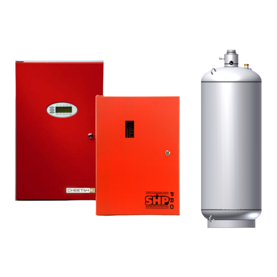
Fike Clean Agent System Installation & Maintenance Manual (140 pages)
w/ FM-200, GCA and DOT / TC Containers
Brand:
Fike
| Category:
Laboratory Equipment
| Size: 3 MB
Table of Contents
Table of Contents
5
Introduction
11
Section 1 - Equipment
13
Agent
13
Performance
13
USE and LIMITATIONS
14
Exposure
14
Exposure Limits
14
Toxicity
15
Noise
15
Turbulence
15
Chilling
15
Visibility
15
Pressure
15
Agent Storage Containers
16
Rupture Disc
16
Containers W/ 1" (25Mm) Valve
17
Containers W/ 2 ½" (65Mm) Valve
19
Floor Mounting Kits
20
Containers W/ 3" (80Mm) Valve
21
1.5.4.1 Mounting Straps
22
Items Furnished W/ Containers
23
Nameplate
23
Siphon Tube
23
Victaulic Coupling & Nipple
23
Pressure Gauge
23
Pressure Gauge Adapter
24
Agent Fill Valve
24
Agent Release Module (ARM)
25
Mounting Hardware for GCA & ARM
25
Gas Cartridge Actuator (Gca)
26
Container Accessories
27
Liquid Level Indicator (Lli)
27
Low Pressure Switch
28
Reload Kits
28
Reload Kit - 1" Valve
29
Reload Kit - 3" Valve
31
Container Ordering Format
32
Discharge Nozzles
33
1.10.1 Pre-Engineered Discharge Nozzles
33
1.10.2 Engineered Discharge Nozzles
34
Check Valves
35
Caution / Advisory Signs
36
System Releasesign
36
Control System & Accessories
37
1.13.1 Control Panels
37
Manual Acturator
37
Section 2 - System Design
39
Determine Hazard Type
39
Determine Concentration Percentage
39
Class B Flammable Liquids-Automatically or Manually Activated System
40
Safety Recommendations
40
Normally Occupied Spaces
40
Normally Non-Occupied Spaces
40
All Spaces
40
Determine Agent Quantity
41
Determine the Hazard Volume
41
Calculate Agent Required
41
Additional Considerations
44
Tee Design Factor
44
Altitude Correction Factors
46
Determine Actual Concentration at Maximum Temperature
46
Leakage
47
System Design Concept
48
Pre-Engineered Systems Concept
48
Engineered Systems Concept
48
Modular Systems
48
Central Storage Systems
48
Container Selection
49
Container Size and Fill Range
49
Container Location(S)
50
Storage Temperature Limitations
50
Nozzle Selection
51
System Type
51
Nozzle Flow Rates
51
Engineered Nozzles
52
Nozzle Area Coverage
52
Nozzle Placement
53
Ceiling Heights Greater than 16'-0" (4.9 M)
54
Nozzle Discharge Obstructions
55
Piping Network Limitations (Engineered Systems)
56
Tee Split Ratios
56
Bullhead Tee
56
Side-Thru Tee
56
Maximum Elevation Differences in Pipe Runs
57
Tee Orientation
58
Estimating Pipe Size (Engineered Systems)
59
2.8.4.1 Discharge Duration
59
2.8.4.2 Minimum Flow Rates
59
Minimum Piping Distance (Engineering Systems)
60
2.8.5.1 Distance from a Tee to an Elbow or Tee
60
2.8.5.2 Distance from an Elbow to a Tee
60
Equivalent Length Values
61
Engineered System Design Limits
62
Percent of Agent in Pipe
62
Location of First Tee
62
Liquid Arrival Time
63
Liquid Runout Time
63
Manifold Options (Engineered Systems)
64
Per-Engineered Systems Design
67
2.11.1 Piping Layout
67
2.11.2 Determining Pipe Sizes
67
Single Nozzle Piping Table - 35 Lb. Thru 215 Lb. Containers
67
Determining the Total Pressure Drop (TPD)
71
Piping Layout Diagram
71
Total Pressure Drop (TDP) Calculation
72
2-Asingle Nozzle Factors Table
72
2-Btwo Nozzle Factors Table
74
2-Cfour Nozzle Factors Table
76
Section 3 - Sample Problem
79
Determine Hazard Volume
79
Calculate Agent Required
80
Determine Concentration at Maximum Temperature
80
Establish System Concept
81
3.3.1 Container Selection
81
3.3.2 Nozzles Required
81
Layout Piping Network
83
Sample Flow Calculation
85
Section 4 - System Installation
97
Agent Storage Containers
97
Mounting Details for Vertical / Horizontal Containers
97
Mounting Details 60 Lb. (27 L) Container
100
Mounting Details for Inverted (Spherical) Containers
100
Mounting Details 125 Lb. (51 L) Container
100
Mounting Details 215 Lb. (90 L) Container
101
Discharge Piping Connections
103
1" (25Mm) Valve Connections
103
2-1/2" (65Mm) Valve Connections
103
3" (80Mm) Valve Connections
104
Manifolds
104
1" NPT Check Valve Installation
106
Piping and Fitting Materials
107
Pipe Size Changes
108
4.4.1.1 Pipe Size Change at a Tee
108
4.4.1.2 Pipe Size Change at an Elbow
108
4.4.1.3 Pipe Size Change at a Coupling
108
Installing Main Discharge Piping
108
Nozzle Installation
109
360° Nozzles
110
Nozzle Set Screw Installation
110
Gas Cartridge Actuator (Gca) / Agent Release Module (Arm)
111
2-1/2" (65 MM) Valve (Inverted Container) GCA Installation
111
Container Electrical Connections
113
Gas Cartridge Actuator (GCA) Safety Recommendations
114
Gas Cartridge Actuator (GCA) Installation Procedure
115
Low Pressure Switch
116
Low Pressure Switch Wiring
117
Section 5 - Final System Checkout
119
Hazard Area Check
119
Area Configuration
119
Area Leakage
119
Enclosure Integrity - Door Fan Testing
119
Containers
120
Discharge Piping
120
Nozzles
120
Auxiliary Functions
120
Section 6 - System Maintenance
121
Discharge Piping
121
Discharge Nozzles
121
Agent Storage Containers
121
Gas Cartridge Actuators
122
Container Test and Inspection
122
Pressure Gauge & Low Pressure Switch Maintenance
123
Replacing a Pressure Gauge or Low Pressure Switch
123
Adding a Low Pressure Switch
123
Advertisement
Advertisement
Related Products
Fike Cheetah Xi
Fike CIE-A-200
Fike CEREX
Fike CIE-A-400
Fike Categories
Security Sensors
Control Panel
Control Systems
Control Unit
Fire Alarms
More Fike Manuals
Login
Sign In
OR
Sign in with Facebook
Sign in with Google
Upload manual
Upload from disk
Upload from URL