Sign In
Upload
Manuals
Brands
Festo Manuals
DC Drives
CMMT-ST-SW
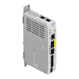
Festo CMMT-ST-SW Manuals
Manuals and User Guides for Festo CMMT-ST-SW. We have
1
Festo CMMT-ST-SW manual available for free PDF download: Original Instructions Manual
Festo CMMT-ST-SW Original Instructions Manual (616 pages)
Servo drive
Brand:
Festo
| Category:
DC Drives
| Size: 7 MB
Table of Contents
Festo — CMMT-ST-SW
2
Table of Contents
3
1 About this Document
12
Applicable Documents
12
Product Version
13
Safety Instructions
13
Conventions
13
2 CMMT-ST Plug-In
13
CMMT-ST Getting to Know the Plug-In
13
Overview
13
Festo — CMMT-ST-SW
14
Interface
15
Overview
15
Contexts
15
Toolbar
16
Navigator
19
Working Area in the Title Bar
19
Display of Real-Time Values
19
Cross-Context Elements and Error Messages
19
Adorner
19
Pop-Up for Automatic Values Changes
21
Key Combinations
21
Basic and User Units
22
Automatic Data Synchronisation
23
Working with CMMT-ST the Plug-In
23
Open Plug-In
23
Connecting the Plug-In to the Device
23
Connection Control
23
Establishing and Disconnecting a Connection
26
Synchronising Device Data
31
Synchronising the Configuration and Parameters
31
Device Control (Master Control)
34
Initial Commissioning Assistant
34
Overview
34
Drive Configuration
36
Setting Application Data
41
Activating the Hardware Switch
43
Setting the Referencing
43
Setting the Software Limit Positions
44
Parameterisation
46
Interface
46
Entering Parameters
49
Drive Configuration
51
Device Settings
56
Fieldbus
57
Digital I/O
57
Encoder Interface
58
Axis 1
59
Motor
59
Gearbox
60
Axis
60
Record List
64
Monitoring Functions
67
Open Loop
68
Closed Loop
68
Auto Tuning
72
Assistant for Auto-Tuning
73
Notch Filter
76
Feed Forward Control
76
Jog Mode
77
Parameter List
77
Diagnosis
78
Interface
78
Device State
78
I/O State
80
Error Log
81
Error Classification
82
Trace Configuration
83
Trace Display
86
Auto Tuning (Evaluation)
93
Control
95
Interface
95
Manual Movement
95
Record List
97
Integrating a Device in a Festo Controller
98
3 Product Configuration
101
Controllers
101
Communication Interfaces
101
Firmware
101
Cia 402
103
Parameter Set
104
Master Control
105
Device Services
106
Reset Device
107
Controller Parameter Set Switchover
107
Saving Zero Point Offset
107
Request Reinit
107
Delete Parameter Set
108
Save Parameter Set
108
Cam Controller 0
108
Cam Controller 1
109
Position Capture (Touch Probe) 0
109
Position Capture (Touch Probe) 1
109
Fundamentals of Parameterisation
109
Depiction of the Parameters
109
Data Types
110
Depiction of the Device-Profile-Specific Objects
111
Measuring Units
112
Defined Measuring Units
112
Configurable Measuring Units ("User Unit")
112
Scaling of Internal Units for the Fieldbus ("Factor Group")
115
Measuring Reference System
120
Function
120
Cia 402
125
Drive Configuration
125
Motor Configuration
125
Function
125
Parameter and Diagnostic Messages for Motor Data from the User Configuration
127
Cia 402
132
Parameter and Diagnostic Messages for Motor Data from the EEPROM Memory
133
Cia 402
138
Active Motor Data Parameters
140
Cia 402
145
Brake Control
146
Function
146
Parameters and Diagnostic Messages
149
Cia 402
152
Encoder Configuration
152
Function
152
Encoder Parameters and Diagnostic Messages
153
Cia 402
161
Parameters of Digital Incremental Encoders (A, B and N Signals)
162
Cia 402
164
Parameters of Encoders with the Biss C Protocol
164
Cia 402
166
Parameters of the Actual Value Management
166
Cia 402
167
Parameters of the Direction of Rotation Manager
168
Cia 402
169
Parameters of the Commutation-Angle Detection
169
Cia 402
172
Replacement of Motors Without an Electronic Data Sheet
172
Gear Unit
173
Function
173
Cia 402
177
Digital Inputs and Outputs
179
Function
179
Cia 402
183
Protective Functions
184
I²T Monitoring of the Power Output Stage
184
Cia 402
187
I²T Monitoring of Motor
188
Cia 402
190
Temperature Monitoring of the Servo Drive
190
Cia 402
192
System Monitoring
193
Mains and DC Link Monitoring
193
Mains Voltage Monitoring
193
Monitoring of the DC Link Voltage
194
Return Energy Feed
197
4 Motion Control
200
Operating Modes
200
Finite State Machine
200
Operating Modes for Performing Motion Commands
203
Dynamic Operating Mode Switch
204
Cia402
205
Positioning Mode(PP)
206
Function
206
Cia 402
209
Velocity Mode (PV)
213
Function
213
Cia 402
216
Force/Torque Mode (PT) with or Without Holding Brake
220
Function
220
Cia 402
222
Cyclic Synchronised Positioning Mode (CSP)
225
Function
225
Cia 402
229
Cyclic Synchronised Velocity Mode (CSV)
233
Function
233
Cia 402
236
Cyclic Synchronised Force/Torque Mode (CST)
239
Function
239
Cia 402
241
Switch-On/Off Behaviour and Closed-Loop Controller Enable
244
Function
244
Cia 402
251
Stop
251
Function
251
Cia 402
253
Hold
254
Function
254
Cia 402
255
Homing
255
Function
255
Timing
262
Homing Methods
265
Method 37: Current Position
266
Method 33/34: Current Position with Zero Pulse in Negative/Positive Direction
266
Method 17/18 Negative/Positive Limit Switch
267
Method 1/2: Negative/Positive Limit Switch with Zero Pulse
268
Method 23/27: Positive/Negative Reference Switch
269
Method 7/11: Positive/Negative Reference Switch with Zero Pulse
270
Method -23/-27: Positive/Negative Stop/Limit Switch with Run to Reference
271
Method -17/-18 Negative/Positive Stop
272
Method -1/-2 Negative/Positive Stop with Zero Pulse
273
Travel to Axis Zero-Point
274
Cia 402
275
Command for Record Selection
279
Record Selection
279
Function
279
Record Sequencing
288
Function
288
Monitoring of Events
293
Function
293
Cia 402
295
Jog Mode
296
Function
296
Cia 402
302
5 Motion Monitoring
304
Motion Monitoring Functions
304
Target Window Reached
310
Cia 402
313
Following Error
313
Cia 402
316
Target Area Monitoring
316
Cia 402
319
Hardware Limit Switch Reached
319
Cia 402
321
Software Limit Position Reached
322
Cia 402
325
Standstill Monitoring
325
Cia 402
328
Stop Reached
329
Cia 402
331
Stroke Limit Reached
331
Cia 402
333
Speed Monitoring (Spinning Protection)
334
Cia 402
334
Pushback Monitoring
335
Cia 402
336
Remaining Distance Monitoring
336
Cia 402
337
Trajectory Completed
337
Reference Switch Activated
338
Function
338
Cia 402
339
Directional Lock
339
Function
339
Cia 402
340
6 Control
341
Cascade Controller
341
Function
341
Position Controller
342
Cia 402
345
Velocity Control
346
Cia 402
349
Current Regulator
349
Cia 402
355
Control Parameter Sets
356
Cia 402
358
Limitations
359
Limitation of Application
359
Cia 402
362
Control Limitation
362
Cia 402
367
Torque Limitation
369
Cia 402
371
Pilot Control (Setpoint Value Control)
372
Setpoint Value Connection
372
Inertia and Friction Compensation
377
Cia 402
380
Notch Filter
381
Function
381
Cia 402
383
Auto Tuning
384
Function
384
Cia 402
390
Test Run
391
Cia 402
394
7 Technology Functions
394
Cam Controller (Position Trigger)
394
Function
394
Cia 402
407
Position Detection (Touch Probe)
408
Function
408
Cia 402
420
Open-Loop Operation
423
Cia 402
427
Field Weakening
427
Cia 402
428
8 Safety Signals
428
Function
428
Cia402
430
9 Diagnostics and Fault Clearance
430
Diagnostics Options
430
Classification of Diagnostic Events
431
Diagnostic Status
434
Cia 402
435
Servo Drive Messages
435
Status of Messages
435
Structure of Messages
436
Message Directory
438
Error Memory
438
Acknowledging Messages and Errors
438
Diagnostic Messages with Information for Fault Clearance
440
Recording Measuring Data (Trace)
498
Cia 402
506
Condition Monitoring
508
Mileage Counter
508
Cia 402
509
Load Change Counter
510
Cia402
511
Operating Hour Counter
511
Cia402
512
10 Web Server
512
Function
512
Cia 402
514
11 Ethercat
515
General
515
ETG Standards
515
Ethercat Communication
515
Overview of Ethercat Communication and Synchronisation
515
Ethercat Bus
518
Ethercat Slave Controller ESC
518
Protocol
518
Ethercat Final State Machine
520
Sync Manager
523
Sync Manager Communication
523
Cia 402
525
Synchronisation
525
Cia 402
529
Distributed Clocks DC (Distributed Clocks)
530
Process Data Communication
531
PDO Mapping
532
Function: Rxpdo1 Mapping
532
Function: Txpdo1 Mapping, Axis 1
532
Function: Txpdo2 Mapping, Ethercat, Diagnostic History
533
Function: Txpdo3 Mapping, Ethercat, DC Time Stamp
534
Parameters and Diagnostic Messages
535
Cia 402
536
Mailbox Communication
536
SDO Communication
537
SDO Write Command (SDO Download/Download SDO)
537
SDO Read Command (SDO Upload/Upload SDO)
538
SDO Error Message (Abort SDO Transfer Request)
538
Emergency Communication
540
Cia 402
541
Error Finite State Machine
541
Ethernet over Ethercat-Communication (Eoe)
547
Objects Reference List
548
Advertisement
Advertisement
Related Products
Festo CMMT-AS-C2-11A-P3 S1 Series
Festo CMMT-AS-C3-11A-P3 S1 Series
Festo CMMT-AS-C5-11A-P3 S1 Series
Festo CMMT-ST-C8-1C-...-S0 Series
Festo CMMT-ST-C8-1C Series
Festo CMMT-ST-C8-1C-EC-S0
Festo CMMT-ST-C8-1C-EC-PN
Festo CMMT-ST-C8-1C-EC-EP
Festo CMMT-ST-C8-1C-EC-EC
Festo CMMT-AS-C7/12-11A-P3-S1
Festo Categories
Industrial Equipment
Control Unit
Controller
Touch terminals
DC Drives
More Festo Manuals
Login
Sign In
OR
Sign in with Facebook
Sign in with Google
Upload manual
Upload from disk
Upload from URL