Sign In
Upload
Manuals
Brands
Festo Manuals
DC Drives
8061196
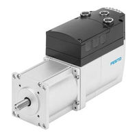
Festo 8061196 DC Servo Motor Manuals
Manuals and User Guides for Festo 8061196 DC Servo Motor. We have
1
Festo 8061196 DC Servo Motor manual available for free PDF download: Operating Instructions Manual
Festo 8061196 Operating Instructions Manual (140 pages)
Integrated drive
Brand:
Festo
| Category:
DC Drives
| Size: 4 MB
Table of Contents
Table of Contents
3
1 Introduction
7
2 Safety and Requirements for Product Use
10
Safety
10
General Safety Instructions
10
Intended Use
11
Requirements for Product Use
11
Transport and Storage Conditions
11
Technical Prerequisites
12
Training of Qualified Personnel
12
Product Conformity and Approvals
12
3 Product Description
13
Product Overview
13
General Features of the Product
14
Scope of Delivery
15
System Structure
16
Software for Configuration and Commissioning
17
FCT (Festo Configuration Tool)
17
Web Server
17
Connections and Display Components
18
Drive Functions
19
Dimension Reference System
20
Homing
23
Jog Mode
31
Teach-In Mode
33
Positioning Mode
33
Velocity Mode
36
Force/Torque Mode
40
Stop (Halt), Quick-Stop
42
Holding Brake (Only EMCA-EC
43
Operational Principle for Record Selection
44
Record Switching
45
Record Sequencing
47
Monitoring of the Drive Behaviour
48
Messages
48
Comparators
51
Protective Functions
54
Error Management
54
Diagnostic Memory
56
Interfaces
56
Ethernet Interface [X1]
56
STO Interface [X6]
58
Functions of the Base Inputs/Outputs
58
Functions of the Additional Inputs/Outputs
64
Control Via the I/O Interface
68
Establishing the Ready Status
68
Set Mode for the I/O Interface
68
Enabling and Disabling the Closed-Loop Controller
69
Acknowledge Errors
70
Execute Homing
71
Jog, Teach (Mode 1)
72
Start Record (Mode 0)
73
Start, Stop and Continue Record (Mode 0)
75
Start and Stop Record, Delete Remaining Path (Mode 0)
76
Record Switching
77
Release Holding Brake (Only EMCA-EC
77
4 Assembly
78
Dimensions
78
Performing Mounting
79
5 Installation
81
Safety Instructions
81
EMC-Compliant Wiring
82
Ethernet Interface [X1]
82
Connection of Plugs [X4]
84
Power Supply [X4]
87
Braking Resistor [X5]
89
STO Interface [X6]
90
Limit or Reference Switch [X7], [X8]
91
I/O Interface [X9]
92
External Battery [X10]
94
Requirements for Ensuring IP Degree of Protection
94
6 Commissioning
95
Notes on Commissioning
95
FCT (Festo Configuration Tool)
95
Installing FCT
95
Starting FCT
96
Notes on Commissioning with FCT
96
Network Connection Via Ethernet
97
Displaying or Changing Network Configuration
99
Security in the Network
99
Master Control
100
Online Connection with the Web Server
102
Commissioning Steps
103
Configuration and Parameterisation
103
Checking STO Function
104
Checking Signal Characteristics of the Limit and Reference Switches
104
Providing Required Signals (Digital I/Os)
104
Checking Direction of Rotation/Travel Direction
106
Execute Homing
107
Testing Positioning Behaviour (Test Mode)
107
Optimising Controller Setting (Optional)
107
Completing Commissioning
107
Saving or Loading Parameter File
108
Instructions for Operation
109
Maximum Write Cycles of the Flash Memory
109
7 Diagnostics and Fault Clearance
109
Access to the Diagnostic Memory
110
Diagnostics Via Leds
111
Behaviour During the Switch-On Phase
111
Behaviour in the Operating Phase
112
Identification Sequence Active
112
Behaviour with Errors in the Firmware Update Phase
112
Diagnostic Messages, Causes and Remedies
112
Explanations for the Diagnostic Messages
112
Diagnostic Messages with Information for Fault Clearance
114
Problems with the Ethernet Connection
129
Other Problems and Remedies
130
8 Maintenance, Care, Repair and Replacement
130
Maintenance and Care
130
Disassembly
131
Repair
132
Replacement and Disposal
132
Disposal
132
9 Technical Appendix
132
Technical Data
132
General Technical Data
132
Product Conformity and Approvals
133
Mechanical Data
133
Operating and Ambient Conditions
133
Data for the Integrated Motor
135
Data for the Integrated Rotor Position Encoder
135
Holding Brake (Only EMCA-EC
136
Ethernet Interface [X1]
136
Power Supply [X4]
136
Braking Resistor [X5]
137
STO Interface [X6]
137
Reference or Limit Switch [X7], [X8]
137
I/O Interface [X9]
137
Connection for External Battery [X10] (Only EMCA-EC-67
138
Materials
139
Advertisement
Advertisement
Related Products
Festo 8030600
Festo 8030613
Festo 8030602
Festo 8030616
Festo 8030603
Festo 8030619
Festo 8030621
Festo 8030622
Festo 8030609
Festo 8030612
Festo Categories
Industrial Equipment
Control Unit
Controller
Touch terminals
DC Drives
More Festo Manuals
Login
Sign In
OR
Sign in with Facebook
Sign in with Google
Upload manual
Upload from disk
Upload from URL