Sign In
Upload
Manuals
Brands
Festo Manuals
Terminal Block
174335
Festo 174335 Manuals
Manuals and User Guides for Festo 174335. We have
1
Festo 174335 manual available for free PDF download: Electronic Manual
Festo 174335 Electronic Manual (184 pages)
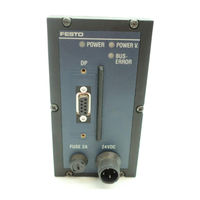
Valve terminal types 03/04-B Valve terminal with field bus connection PROFIBUS-DP 12 MBaud
Brand:
Festo
| Category:
Terminal Block
| Size: 3 MB
Table of Contents
Table of Contents
5
Designated Use
8
Additional Modules for this Valve Terminal
9
Service
11
Target Group
11
Important User Instructions
12
Abbreviations
14
Additional Instructions
16
Manuals for this Valve Terminal
16
1 Summary of Components
17
Summary of Components
18
Summary of Multifunctional Festo Valve Terminals
19
Description of Components
20
Types 03/04-B: Electric Modules
20
1.2.1 T Ypes03/04-B: Electricmodules
21
Type 03: MIDI Pneumatic Modules
21
1.2.2 T Ype 03: MIDI Pneumatic Modules
22
Type 03: MAXI Pneumatic Modules
22
1.2.3 T Ype 03: Maxipneumatic Modules
23
Type 04-B: ISO Pneumatic Modules
23
1.2.4 T Ype 04-B:ISO Pneumatic Modules
24
Method of Operation
24
2 Fitting
27
Fitting the Modules and Components
29
Earthing the End Plates
30
2.1.1 Earthingthe End Plates
32
Fitting Onto a hat Rail (Type 03)
32
Installation
38
General Connection Technology
39
Cable Selection for Field Bus Line
40
Cable Selection for Power Supply
40
Connecting the Cable to the Plug/Sockets
41
Bus Nodes
44
Opening and Closing the Node
44
Configuring the Valve Terminal
46
Setting PROFIBUS Addresses and Voltage Monitoring
47
Overview of Possible PROFIBUS Addresses
49
Field Bus Baud Rate and Field Bus Length
51
Switching on the Power Supply
52
Calculating the Current Consumption
53
Connecting the Power Supply
55
Connecting the PROFIBUS DP Interface
60
Screening/Shield Connection
62
Bus Connection with Terminating Resistors
63
Connection for Fibre Optic Cable (FOC)
65
Commissioning
68
Addressing and Configuring the Valve Terminal
69
Ascertaining the Configuration Data
69
Address Assignment of the Valve Terminal
72
Address Assignment after Extension/Conversion
77
SIEMENS: Bus Configuration and Addressing
79
Switching on the Power Supply
79
Information for Commissioning
80
Preparations for COM PROFIBUS 3.X and
88
Station Selection with COM PROFIBUS
89
Station Selection with COM PROFIBUS
93
Configuration Examples for COM PROFIBUS
97
Address Allocation of Inputs and Outputs
99
STEP 7 V4.X / V 5.0 - Hardware Configurator
101
General DP Master: Bus Configuration and Addressing
110
General Commissioning Instructions
110
Information for Commissioning (General DP Master)
111
Switching on the Power Supply
111
Diagnosis and Error Treatment
124
Summary of Diagnostic Options
125
Diagnosis on the Spot
126
Leds of the Bus Node
126
Leds of the Valves
129
Leds of the Input/Output Modules
131
Test Routines
133
Status Bits
137
Short Circuit/Overload
140
Diagnosis Via PROFIBUS-DP (DP Standard)
141
Summary of Diagnostic Bytes
143
Diagnostic Information
144
Position of Status Bits
149
Behaviour During Faults in the Control System
151
Error Handling
151
Siemens SIMATIC
152
Online Diagnosis with COM PROFIBUS 5.0
154
Diagnostic Buffer STEP 7 (Version 4.X, 5.0)
155
Online Diagnosis with STEP 7
155
Device-Specific Diagnosis with STEP 7 (Version 5.0)
157
Short Circuit/Overload at an Output Stage
158
Type 04-B: Fuses for the Pilot Solenoids
160
Technical Appendix
164
Technical Appendix
165
Technical Data
165
Cable Length and Cross-Sectional Area
168
Examples of Circuitry
174
Power Supply Type 03 - Internal Layout
175
Power Supply Type 04-B - Internal Layout
176
Advertisement
Advertisement
Related Products
Festo 187828
Festo 164960
Festo 187823
Festo 187830
Festo 164965
Festo 187829
Festo 187820
Festo 164972
Festo 187832
Festo 187825
Festo Categories
Industrial Equipment
Control Unit
Controller
Touch terminals
DC Drives
More Festo Manuals
Login
Sign In
OR
Sign in with Facebook
Sign in with Google
Upload manual
Upload from disk
Upload from URL