Sign In
Upload
Manuals
Brands
evertz Manuals
Computer Hardware
X0401H Series
evertz X0401H Series HD Router Manuals
Manuals and User Guides for evertz X0401H Series HD Router. We have
1
evertz X0401H Series HD Router manual available for free PDF download: Instruction Manual
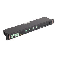
evertz X0401H Series Instruction Manual (118 pages)
Routers
Brand:
evertz
| Category:
Computer Hardware
| Size: 2 MB
Table of Contents
Table of Contents
7
Table 1-1: Router Models and Features
15
Figure 1-1: X0401S Block Diagram
17
Figure 1-2: X0401H Block Diagram
17
Figure 1-3: X-0401-3G Block Diagram
18
How to Use this Manual
18
Overview
18
Glossary
19
Chapter 2: Installation
25
Figure 2-1: X-0401-3G-AES4 Rear Panel Layout with Ethernet Option
25
Figure 2-2: X0401H-AES4 Rear Panel Layout
25
Figure 2-3: X0401H-AES4 Rear Panel Layout with Ethernet Option
25
Figure 2-4: X0401S-AES4 Rear Panel Layout
25
Figure 2-5: X0401S-AES4 Rear Panel Layout with Ethernet Option
25
Installation
25
Rear Panel
25
Standard Definition Digital Video Connections (X0401S)
25
Digital Video Connections (X-0401-3G)
26
Digital Video Connections (X0401S-ATSC)
26
High Definition Digital Video Connections (X0401H)
26
AES Audio Connections
27
Reference Connections
27
Remote Control Connections
27
Table 2-1: Router RS-232 Port Pin Definitions
28
Table 2-2: Router RS-422 Port Pin Definitions
28
Ethernet Network Connections
29
Mounting
29
Power Connections
29
Table 2-3: GPI/O Pin Definitions
29
Connecting the Primary Remote Control Panel (RCP Version)
30
Connecting the Remote Control Panel
30
Power Requirements
30
Table 2-4: Remote Panel Adapter Cable (Part Number WP400RRP)
30
Connecting a Second Remote Control Panel
31
Connecting the General Purpose Inputs and Outputs
31
Table 2-5: Remote Control Panel Extender Cable
31
Connecting the General Purpose Inputs
32
Figure 2-6: General Purpose I/O Schematic
32
Figure 2-7: Powering the General Purpose Input Opto-Isolators from the Router
33
Connecting the General Purpose Outputs
34
Figure 2-8: Powering the General Purpose Input Opto-Isolators from an External Power Supply
34
GPI/O Examples
34
Connecting the Router to a Grass Valley Ten XL ASCII Control Device
35
Controlling the Router Using the External Serial Protocol
35
Controlling the Router Using Vistalink
36
Table 2-6: Master 0401 to Slave 0401 Cable - RS-232 Configuration
36
Table 2-7: Master 0401 to Slave 0401 Cable - RS-422 Configuration
36
Table 2-8: Standard RJ45 Wiring Colour Codes for "Straight Through" Cables
37
Figure 2-10: Crossover Cable Wiring Diagram
38
Chapter 3: Operation
43
Figure 3-1: Front Panel Layout
43
Operation
43
Overview of the Front Panel Display and Controls
43
Setup Key Group
43
Video Router Controls
43
Audio Follow Video Switching (AFV)
44
Front Panel Display Messages
44
Overview of Front Panel Operation
44
Breakaway Audio on an Audio Follow Video Group
45
Front Panel Setup Menu
45
Figure 3-2: Overview of the Setup Menu
46
Navigating the Setup Menu
46
Configuring the Router References
48
Front Panel Setup Menu - Main Menu
48
Setting up the Video Reference
49
Table 3-1: High Definition Video Standards with Valid Reference Video Standards
50
Table 3-2: 3G Level a and Level B Video Standards with Valid Reference Video Standards
51
Setting up the Video Line Synchronizer Timing
52
Setting up the Video Output Timing
52
Configuring the Switch Line
53
Configuring the Video and Audio Transitions
53
Setting up the AES Audio Reference Reference
53
Figure 3-3: Switch Line Selection in 59.94 Hz Field Rate Systems
54
Figure 3-4: Switch Line Selection in 50 Hz Field Rate Systems
54
Enabling the AES Audio Softswitch for Clean Audio Switches
55
Enabling the Embedded Audio Softswitch for Clean Audio Switches
55
Enabling the Video Line Synchronizer for Clean Video Switches
55
Configuring the Router Video Standard (Softswitch Equipped Routers Only)
56
Configuring the Video and Audio Inputs
56
Configuring Which Inputs Are Active
57
Configuring When There Is no Video Input Present
58
Labelling the Video and Audio Inputs
58
Uploading/Downloading Input Labels from a Text File
58
Changing the Input Labels from the Front Panel
59
Configuring the Video Outputs
59
Selecting the Reclocking Mode of the Video Outputs (X0401S, X0401H and X-0401-3G Series)
59
Configuring the General Purpose Inputs (Gpi)
60
Manually Activating All the Bypass Relays
60
Manually Activating the Bypass Relays
60
Selecting the Reclocking Mode of the Video Outputs (X0401S-ATSC Series)
60
Configuring the Encoding Mode for the GPI Inputs
61
HEX GPI Encoding
61
Re-Enabling the GPI Functions
61
Standard GPI Encoding
61
Table 3-3: Standard GPI Encoding Functions
61
Temporarily Disabling the GPI Functions
61
AFV HEX GPI Encoding
62
Standard 2 GPI Encoding
62
Table 3-4: HEX GPI Encoding Functions
62
Table 3-5: HEX Input Selection (HEX and AFV HEX Encoding)
62
Table 3-6: AFV HEX GPI Encoding Functions
62
Configuring Whether the GPI Inputs Are Edge or Level Activated
63
Programming the GPI Input Functions
63
Table 3-7: Standard GPI Encoding Functions
63
Configuring the Encoding Mode for the GPO Outputs
64
Configuring the General Purpose Outputs (Gpo)
64
HEX GPO Encoding
64
Re-Enabling the GPO Functions
64
Temporarily Disabling the GPO Functions
64
Configuring Whether the GPO Outputs Are Latched or Momentary
65
Programming the GPO Output Functions
65
Table 3-8: HEX Encoded Output Tallies
65
Configuring the Remote Control Port Operation
66
Selecting the Baud Rate for the Remote Control Port
66
Selecting the Serial Data Format for the Remote Control Port
66
Selecting the Serial Control Address
67
Selecting the Serial Data Control Mode
67
Selecting the External Remote Control Protocol
68
Selecting the GVG PS Status
68
Recalling a Saved User Preset Configuration
69
Restoring the Factory Default Settings
69
Saving and Recalling Configuration Presets
69
Managing the Miscellaneous Configuration Items
70
Saving the Router Configuration to a User Preset
70
XPT Panel Lock
70
Network Configurations
71
Configuring DHCP Mode
72
Setting the Broadcast Address
72
Setting the Gateway
72
Setting the IP Address
72
Setting the Net Mask
72
Setting the Trap Addresses
73
How to Update the Router Firmware
74
Managing the Router Firmware
74
Reading the Router Firmware Version
74
Setting the Community Strings
74
Chapter 4: Technical Description
77
HD Video Inputs
77
SD Video Inputs
77
SD Video Outputs
77
Specifications
77
Technical Description
77
Video Specifications (X0401H Series)
77
Video Specifications (X0401S Series)
77
HD Video Outputs
78
Video Inputs
78
Video Specifications (X0401-3G Series)
78
Video Inputs
79
Video Ouputs
79
Video Outputs
79
Video Specifications (X0401S-ATSC Series)
79
AES Audio Inputs (AES4 Versions Only)
80
AES Audio Outputs (AES4 Versions Only)
80
DARS Reference (Softswitch and Embedded Softswitch Equipped Routers Only)
80
GPI Control Port
80
Serial Remote Control
80
Video Reference
80
Configuring the Remote Control Serial Port
81
Electrical
81
Ethernet Port (Routers Fitted with +ET Option Only)
81
Jumpers
81
Physical
81
Remote Control Panel Port
81
Configuring the Router for a DARS Reference
82
Step 1 - Terminal Program Setup
82
Table 4-1: Serial Upgrade Cable for Use When Remote CTL Port Is Set to RS-422 Configuration
82
Upgrading Firmware
82
Step 2 - Invoke Upload Mode Via the Front Panel
83
Step 3 - Invoke Upload Mode from the Terminal Program
83
Step 4 - Uploading the New Firmware
84
Step 5 - Completing the Upgrade
84
Step 1 - Terminal Program Setup
85
Uploading Router Input Labels from a Text File
85
Step 2 - Download the Current Labels from the Router
86
Step 3 - Editing the Label Text File
86
Sample Label Text Files
87
Step 4 - Upload the New Label File to the Router
87
Changing the Fuses
88
Servicing Instructions
88
Chapter 5: Serial Control
90
Definitions
91
Gvg Ten-Xl Ascii Protocol
91
Remote Control of the Routers
91
Serial Data Format
91
Table 5-1: Reserved Words in GVC TEN-XL ASCII Protocal
91
Command Formats
92
Read or Query Command
92
Reply Command String
92
Table 5-2: Crosspoint Numbers and Their Internal Source Numbers
92
Table 5-3: ASCII Command Definitions
92
Write or Take Command
92
Command Examples
93
Input Selection - Audio Follow Mode
93
Input Selection - Breakaway Mode
93
Router Status Request
93
Performer Protocol
94
Table 5-4: Performer ASCII Command Definitions
94
Table 5-5: Common ASCII Performer Command Parameters
95
Table 5-6: Command Examples
96
Chapter 6: Vistalink® Remote Monitoring/Control
99
Figure 6-1: General Monitoring Tab for the X0401-H/S
99
General Monitoring and Control Parameters for X0401-H/S
99
Vistalink® Remote Monitoring/Control
99
What Is Vistalink
99
Figure 6-2: General Monitoring Tab for the X-0401-3G
100
General Monitoring and Control Parameters for X-0401-3G Only
100
Table 6-1: X0401-H/S Parameter Description
100
Figure 6-3 : Video Miscellaneous Control Tab
101
Table 6-2: General Parameters
101
Video Miscellaneous Control Tab
101
Figure 6-4: Video Input Configuration Tab
102
Table 6-3: Video Miscellaneous Control Parameters
102
Video Input Configuration Tab
102
Figure 6-5: Video Output Configuration Tab
103
Table 6-4: Video Input Configuration Parameters
103
Video Output Configuration
103
Figure 6-6: Audio Configuration Parameters
104
Table 6-5: Video Output Configuration Parameters
104
Audio Configuration
105
Figure 6-7: GPIO Configuration Tab
105
Gpio Configuration
105
Table 6-6: Audio Configuration Parameters
105
Figure 6-8: Miscellaneous Control Configuration Tab
106
Miscellaneous Control Configuration
106
Table 6-7: GPIO Configuration Parameters
106
Faults
107
Figure 6-9: Faults Configuration Tab
107
Table 6-8: Miscellaneous Control Configuration Parameters
107
Figure 6-10: Video Faults Configuration Tab
108
Table 6-9: Faults Configuration Parameters
108
Video Faults
108
Audio Faults
109
Figure 6-11: Audio Faults Configuration Tab
109
Table 6-10: Video Faults Configuration Parameters
109
Table 6-11: Audio Faults Configuration Parameters
109
Video and Audio Output Configurations
111
All Input Signals Are Timed to Reference
113
Figure 7-1: Timing Example 1 - Inputs in Time with Reference
113
Figure 7-2: Timing Example 2 - Inputs in Time with Reference
114
Input Signals Are Timed to Within +/- 1 Line of Reference
114
All Input Signals Are Timed Together but Delayed 5 Lines from Reference
115
Figure 7-3: Timing Example 3 - Inputs in Time but Delayed 5 Lines from Reference
115
All Input Signals Are Timed Within a Range of +/- 1 Line
116
All Input Signals Are Timed Within a Range of +/- 1 Line from
116
All Input Signals Are Timed Within a Range of +/- 1 Line from each Other but Delayed 5 Lines from Reference
116
Figure 7-4: Timing Example 4 - Inputs Not in Time and Delayed from Reference
116
From each Other but Delayed 5 Lines from Reference
116
All Input Signals Are Timed Within a Range of +/- 1 Line
117
Figure 7-5: Timing Example 5 - Bypass Router for Production Switcher
117
From each Other but Delayed 5 Lines from Reference
117
Advertisement
Advertisement
Related Products
evertz X0400 Series
evertz X0401S Series
evertz X0401-3G Series
evertz X0401S-ATSC Series
evertz X-0808-OO
evertz X1201S
evertz X-HD9504
evertz X-HD9512
evertz X1201H+HSS
evertz X1202S-AES4+SS
evertz Categories
Media Converter
Network Hardware
Amplifier
Transmitter
Receiver
More evertz Manuals
Login
Sign In
OR
Sign in with Facebook
Sign in with Google
Upload manual
Upload from disk
Upload from URL