Sign In
Upload
Manuals
Brands
evertz Manuals
Receiver
MultiFrame 7807LR-2
User Manuals: evertz MultiFrame 7807LR-2 Fiber Receiver
Manuals and User Guides for evertz MultiFrame 7807LR-2 Fiber Receiver. We have
1
evertz MultiFrame 7807LR-2 Fiber Receiver manual available for free PDF download: Manual
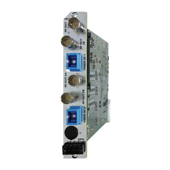
evertz MultiFrame 7807LR-2 Manual (36 pages)
Dual L-Band/Wideband RF Fiber Receiver
Brand:
evertz
| Category:
Receiver
| Size: 0 MB
Table of Contents
Table of Contents
1
Overview
7
Figure 1-1: 7807LR-2/7807LR-2-H Block Diagram
8
Installation
9
Figure 2-1: 7807LR-2/7807LR-2-H Rear Panel
9
7807Lr-2/7807Lr-2-H Connections
10
Care and Handling of Optical Fiber
11
Handling and Connecting Fibers
11
07Lr-2/7807Lr-2-H Specifications
12
Rf Outputs
12
Optical Inputs
12
General Purpose Outputs
12
Electrical
12
Physical
12
Status Indicators and Displays
13
7807Lr-2/7807Lr-2-H Status Indicators
13
Jumper Positions
14
7807Lr-2/7807Lr-2-H Jumpers and Leds
14
Selecting Whether Local Faults will be Monitored by the Global Frame Status
14
Figure 5-1: Location of 7807LR-2/7807LR-2-H Jumpers and Leds
14
Configuring the Module for Firmware Upgrades
15
Factory and Bdm Jumpers
15
Gpo Jumpers
15
Dot-Matrix Display
16
Figure 6-1: Card Edge Menu Structure
20
7807Lr-2/7807Lr-2-H Controlled Parameters
21
Adjusting the Optical Power Alarm Thresholds
21
Adjusting the RF Output Power Alarm and Squelch Thresholds
21
Selecting the Output Gain Mode
22
Adjusting the RF Output Gain
23
Adjusting the AGC Target Level
23
Enabling/Disabling Squelch Mode
24
Setting the Card Edge Display Orientation
24
Resetting Factory Defaults
24
Transmitter Controllable Parameters
24
Adjusting the RF Input Power Alarm Thresholds
25
Adjusting the Internal Transmitter Temperature Alarm Thresholds
25
Adjusting the Input Voltage Alarm Thresholds
26
Adjusting the LNB Current Alarm Thresholds
26
7807Lr-2/7807Lr-2-H Monitored Conditions and Parameters
27
Displaying the Input Optical Power
27
Displaying the Output RF Power
27
Displaying the Squelch Status
27
Transmitter Monitored Parameters
28
Displaying the Presence of the Data Signal
28
Displaying the Input RF Power to the Connected Transmitter
29
Displaying the Gain Mode of the Connected Transmitter
29
Displaying the Gain Level of the Connected Transmitter
29
Displaying the AGC Status of the Connected Transmitter
30
Displaying the RF Drive Status of the Connected Transmitter
30
Displaying the Output Optical Power of the Connected Transmitter
30
Displaying the Laser Status of the Connected Transmitter
31
Displaying Status of the Power Supply Connected to the Transmitter
31
Displaying the Internal Temperature of the Connected Transmitter
31
Displaying the LNB Mode of the Connected Transmitter
32
Displaying the LNB Voltage of the Connected Transmitter
32
Displaying the LNB Current
32
Displaying the Firmware Version of the Connected Transmitter
33
Displaying the Model of the Connected Transmitter
33
Vistalink Remote Monitoring/Control
34
What Is Vistalink
34
VISTALINK Monitored Parameters
35
VISTALINK Controlled Parameters
35
Table 7-1: Vistalink Monitored Parameters
35
VISTALINK Traps
36
Table 7-2: Vistalink Controlled Parameters
36
Table 7-3: Vistalink Traps
36
Advertisement
Advertisement
Related Products
evertz MultiFrame 7807LR-2-H
evertz 7706LR Series
evertz 7708LRA
evertz 7707AR-A12
evertz 7707VR-8-HS
evertz 7707CVR-4
evertz 7707CVR-4-A16
evertz 7708LR
evertz 7707IFRA Series
evertz 7707VAR
evertz Categories
Media Converter
Network Hardware
Amplifier
Transmitter
Receiver
More evertz Manuals
Login
Sign In
OR
Sign in with Facebook
Sign in with Google
Upload manual
Upload from disk
Upload from URL