Sign In
Upload
Manuals
Brands
EURA Manuals
Inverter
E2000-0150 T3
EURA E2000-0150 T3 Manuals
Manuals and User Guides for EURA E2000-0150 T3. We have
1
EURA E2000-0150 T3 manual available for free PDF download: Safety Instructions And Operation Manual
EURA E2000-0150 T3 Safety Instructions And Operation Manual (83 pages)
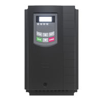
E2000 Series FREQUENCY INVERTER
Brand:
EURA
| Category:
Inverter
| Size: 4 MB
Table of Contents
Table of Contents
2
Index
2
Common Installation
3
Common
4
Specified Application of Frequency Inverters
4
Observe Specific Standards and Rules
4
Handling, Transportation and Storage
5
Installation of the Inverter
5
Electrical Wiring of Frequency Inverters
6
Potential Equalization
7
Insulation Testing
7
Braking Resistors
8
Differential Current Breaker (FI)
8
Basic Rules for Reliable and Safe Operation
9
Inverter Protection-Functions
9
Power-Grid Specification
10
Power Supply – Short Circuit Capability
10
Measurements on Inverter Input and Output
10
Twist All Unshielded Cables
11
EMC: Basics and Recommendations for Installation
11
EMC - Adequate Installation
11
Inverters with UL Mark: Additional Information
12
Product Naming Convention
13
Options Identifier
13
Nameplate
13
Product Data / Product Power Range
13
Mechanical Construction
15
Appearance of an E2000+
16
Technical Data - Inverter Series E2000+
17
Power Range – Framesize
18
Mounting in Cabinet
19
Maintenance and Service
19
Inverter Mounting
19
230V Singlephase Inverter
20
230 V Singlephase Inverter
20
Electrical Connection of E2000+ Inverters
20
400V Threephase Inverter
21
Brake Resistor
22
400V Threephase Inverter - above 22 Kw
22
Recommended Cable Cross Sections, Fuses, Terminal Tightening Torque
23
Earth/Ground Connection
23
Control Terminals – Control Board
25
Inverter Size E1 – E6
25
Inverter Size C3 – C6
25
E2000+_Rev.02 -D- SOFT Rev. 5.09
25
RS485 Terminal
26
Main Terminal
26
Control Terminal Function and Factory Default Configuration
26
E2000+_Rev.02 -D- SOFT Rev. 5.09
27
Sample Set-Up for Inverter 22 Kw, 400V - Framesize
28
E2000+_Rev.02 -D- SOFT Rev. 5.09
28
Control-Board: Hardware and I/O Channel Configuration
29
Digital Input Channels
29
Control-Board Inverter 0,4...22Kw
29
Analogue Input Channels
30
Digital Output Channels
31
Analogue Output Channels
31
Control-Board Inverter 30...400Kw
32
Motor Protection Using PTC/KLIXON: for All Inverter Size
35
Power Supply for Passive Current Loop Sensor
35
7-Segment Display:
36
Status LED
36
Key and Function
36
Operating Panel
36
Display of Function Parameters and Error Codes
37
Remote Operating Panel
37
Parameter Setting
38
Selection of Parameters, Modification and Saving
38
Parameter Group 100: Basic Parameter
39
Internal Speed Reference (Hz)
40
Reference for Accel./Decel. Ramp Time
40
Knee Frequency (Hz)
40
Dead Time During Reversion (Sec.)
40
Display Configuration
41
Parameter, for Calculated Speed Indication (Display)
42
Slip Compensation in V/Hz Mode
43
Factory Default Reset Procedure
44
START / STOP / Running Direction
45
Selection of Speed Reference Sources
45
Parameter Group 200: Inverter Control
45
Combined Speed Control – between Primary/Secondary Speed Reference
46
Combination between Different Speed Reference Channels
48
Two / Three Wire Control for START - STOP - DIRECTION
50
Function Mapping for Digital Output Channels
52
Parameter Group 300: Digital I/O Configuration
52
Activation and Configuration of the "S" Shaped Ramp
53
Frequency Threshold Setting
53
Current Threshold
53
Internal Counter Programming
53
Function Mapping for Digital Input Channels
54
Table: Functions of Digital Inputs
54
Logic Inversion of Digital Inputs
56
Accel./Decel. Ramp Selection - Table 300-2
56
Fixed-Frequencies Selection – Table 300-1
56
Configuration of Analogue Speed Reference Channels
57
Parameter Group 400: Analogue I/O Channel Configuration
57
Panel / Potentiometer Selection
58
Pulse Speed Reference Signal Input Configuration
59
Non-Linear Characteristic for Analogue Channels
59
Analogue Output Configuration
60
Pulse Output DO1
60
Auto-Cycling Parameter
61
Programming of the Individual Fixed-Frequencies
61
Parameter Group 500: Fixed-Frequency, Automatic Cycling Frequencies
61
DC-Brake Function Parameters
62
Current- Voltage Limiting Functions
62
Parameter Group 600: DC-Bake Control / Aux. Functions
62
Brake Chopper Control (Internal Brake Chopper)
64
DC-Voltage Control
64
Power Drop Compensation
64
Independent Motorvoltage Control Via Separate Setpoint
65
Parameter Group 700: Error Handling and Protection Functions
66
Fan Control Mode
67
Inverter/Motor Over-Load Protection
67
Following Graphics, to Show Warning Delay Characteristic
67
Programmable Delay for STOP- DISABLE with STOP Signal through Terminal
67
Fault History
68
Error Event Counters
68
Protection Functions – Configuration
68
Delay for Inverter Error Trip
68
Idling Detection
69
Analogue Signal Interruption Detection
69
Motor Overload Coefficient
69
Overheat Warning Level
69
AUTOTUNING Mode
70
Parameter Group 800: Autotuning – Motor Data Programming
70
Sensorless Vector Speed Controller Parameter
71
Parameter for Permanent Magnet Syncronus Motor Control
71
Hardware MODBUS - Interface
73
Parameter Group 900: RS485 Hardware and Interface Parameters
73
Integrated PID-Controller
74
Parameter Group A00: PID Controller Parameter
74
PID Controller Parameter Setting
76
Specific Pump Controller Parameter
76
Idling / Lack of Water Protection
76
Master / Slave Interchange
76
Emergency Functions
77
Torque Boost for Low Frequencies
78
Set-Point Origin for Torque Control
78
Parameter Group C00: Speed / Torque Control
78
Speed Limiting for Inverter, Working in Torque Control Mode
79
Torque Limiting for Inverter Working in Speed Control Mode
79
Torque / Current Limit for Field Wakening Area
79
E2000+ Diagnosis
80
Digital Inputs: Status Monitoring
80
Analogue Input Value Check
80
Analogue Output Stimulation
80
Advertisement
Advertisement
Related Products
EURA E2000-0110 T3
EURA E2000-0185 T3
EURA E2000-0004 S2B
EURA E2000-0015 S2B
EURA E2000-0022 T3
EURA E2000-0030 T3
EURA E2000-0055 T3
EURA E2000-0550 T3
EURA E2000-0450 T3
EURA E2000-0750 T3
EURA Categories
Door locks
Intercom System
IP Access Controllers
Smoke Alarm
Control Unit
More EURA Manuals
Login
Sign In
OR
Sign in with Facebook
Sign in with Google
Upload manual
Upload from disk
Upload from URL