Sign In
Upload
Manuals
Brands
Esser Manuals
Desktop
8000M
Esser 8000M Fire Alarm System Manuals
Manuals and User Guides for Esser 8000M Fire Alarm System. We have
1
Esser 8000M Fire Alarm System manual available for free PDF download: Operation And Installation Instructions Manual
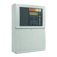
Esser 8000M Operation And Installation Instructions Manual (190 pages)
Fire Alarm Computer
Brand:
Esser
| Category:
Desktop
| Size: 3 MB
Table of Contents
Table of Contents
3
General
4
General View
5
Key Switch / Enabling Operation
6
Function of the Display and Operating Elements
7
Operating Status of the Fire Alarm Control Panel
16
Normal Condition
16
Fire
16
Trouble
17
CPU Failure
17
Disconnection
18
Testmode
18
Operation
19
Function Keys / Selection Menu
19
Display / Display Control
21
Display Priority of the Messages in the Display
23
Info Text / Additional Text and Parameter Display
24
Entering Time/Date
25
Detector Zones
26
Switching on / Resetting a Detector Zone
26
Disconnect a Detector Zone
27
Status of a Detector Zone
28
Detectors
29
Switching on / Resetting a Detector
29
Disconnect a Detector
30
Status of a Detector
31
Controls
32
Switching on a Control Output
32
Disconnect a Control Output
33
Status of a Control Output
34
Common Display of the Status Messages
35
Delay and Verify
36
Delay
37
Verify
37
Alarm Counter
38
Lamp Test
39
Service Level
40
Primary Loop Functions
41
Sensor Functions (Loop)
43
Sensor Functions (Zone/Detector)
45
Installation Instruction
47
Installation Instructions Fire Alarm Computer 8000C / 8000M from Version V2.41
48
Installation Instructions
49
Standards, Guidelines and Instructions for Installation
49
Standards and Guidelines
50
Overview
51
Esserbus -Plus Function
52
Plus
53
Configuration Options FACP 8000C
55
Configuration Options FACP 8000 M
58
Assembly
63
Wallmounting
64
Connection between the Central Housing and the Extension Housing
66
Central Housing
67
Mounting the Cabinet / Installation
69
Extension Housing
72
Extension Housing for Two Rechargeable Batteries (789300/01)
74
Operating Module / Housing Door
75
Opening and Closing the Housing Door
75
Definition of the Primary Loop Number
76
Power Supply Module (Standard / Esserbus -Plus)
78
Basic Module of the FACP 8000C / M
82
Mains Connection
85
1Protective Earth - FACP 8000 C
86
2Protective Earth - FACP 8000 M
87
Connecting the Micro Module
88
Serial Interface
89
Common Trouble Relay
90
Inputs IN1 and IN2
90
Connection of the Cover Contacts
91
DIL Switch S5
92
Reset-Function
92
Connecting the Built-In Printer
93
Field Device Module
94
Connection of the Micro Module
97
Primary Loop Input Pri+/Pri
97
Connecting a Fire Department Operating Panel
98
Connecting the Master Box (Relay K1)
99
1Connecting the Relays K2, K3, K4
102
Extension Module (Part No. 772419)
104
Extension Module (Part No. 772421)
105
Configuration of the FACP 8000C / M with Customer Data Editor
106
Micromodule
107
Technical Data
107
Installation Instructions Micro Modules (V2.41)
110
Analog Loop Modules
111
Analog Loop Module Esserbus
114
Plus (Part No. 804382)
115
Wiring - Esserbus -Plus
116
13 3-Relay Module / 3-Relay Common Trouble Module
118
14 4-Relay Module
122
Master Box Activation Module
124
RS 232 / TTY Module (Serial Interface)
128
17 4-Output Module
130
18 7-Output-P Module / 7-Output-M Module
132
19 4-Zone Module
134
BSL Interface Module
136
Essernet Module
138
Essernet ® Micro Module Hardware Revision E and Higher
142
Esserbus ® Transponder
144
Commissioning / Servicing
145
Technical Data
145
Esserbus ® Analog Loop Module (Part No. 784382)
145
Esserbus ® -Plus Analog Loop Module (Part No. 804382)
145
RS 232/TTY Module (Serial Interface)
146
4-Output Module
146
7-Output Module (Open Collector Outputs)
146
Master Box Activation Module
146
4-Relay Module
147
3-Relay Module / 3-Relay-Sas-Module
147
4-Zone Module
147
BSL Module
147
Essernet ® Module Type 1
148
Essernet ® Module, Type 2
148
Esserbus ® Transponder Ek-12-REL
149
Esserbus ® - Transponder Ek-32AE
149
Esserbus ® - Transponder Ek-1GRP
149
Esserbus ® Transponder Ek-4 IN/2OUT
150
Esserbus ® Transponder Ek-KOM-LMST
150
Commissioning / Servicing Fire Alarm Computer 8000C / M
152
Commissioning / Servicing
153
Status Display
153
Installer Level
155
Installer Level; Primary Loop Function
159
Switching on / Resetting a Primary Loop
161
Testing (the Analog Loop)
162
Detector Replacement
163
Simulation of Detector States
166
Simulation of Control States
168
Query of Additional and Info Texts of Other Control Panels (Remote Text)
170
Printer Function
170
Display of the Event Memory
174
Diagnostic Display
175
Power Supply Values of FACP 8000C / M
175
The Essernet ® Diagnostic Line
176
Meaning of the 3 Digit Error Codes
179
Trouble Messages in the Display
185
Advertisement
Advertisement
Related Products
Esser 8000C
Esser Categories
Desktop
Media Converter
Control Panel
Control Systems
Security Sensors
More Esser Manuals
Login
Sign In
OR
Sign in with Facebook
Sign in with Google
Upload manual
Upload from disk
Upload from URL