Sign In
Upload
Manuals
Brands
Environnement Manuals
Measuring Instruments
AS32M
Environnement AS32M Manuals
Manuals and User Guides for Environnement AS32M. We have
1
Environnement AS32M manual available for free PDF download: Technical Manual
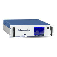
Environnement AS32M Technical Manual (186 pages)
OPTICAL ABSORPTION CAPS NO2 ANALYZER
Brand:
Environnement
| Category:
Measuring Instruments
| Size: 5 MB
Table of Contents
Table of Contents
4
Chapter 1 General - Characteristics
9
Figure 1-1 - Environnement S.A. AS32M
9
Figure 1-2 - Keyboard and Display
9
Figure 1-3 - Rear Panel of AS32M Standard Model
9
Figure 1-4 - Rear Panel of AS32M Equipped with the Solenoid Valve Option
9
Figure 1-5 - Rear Panel of AS32M Equipped with the Permeation Bench Option
9
Figure 1-6 - Internal View of AS32M of AS32M Standard Model
9
Figure 1-7 - Internal View of AS32M Equipped with the Solenoid Valve Option
9
Figure 1-8 - Internal View of AS32M Equipped with the Permeation Bench Option
9
Figure 1-9 - Links between Units
9
General Characteristics
10
Chapter 2 Principle of Operation
25
Theoretical Basis: Optical Cavity
25
Measurement Principle
25
Description of the Main Modules
25
Simplified Flow Chart of Main Program
25
Automatic Response Time
25
Ethernet Output and Usb Port (Dnp-Arm7 Board)
25
Figure 2-1 - Diagram of the Optical Cavity
25
Figure 2-2 - General Principle Diagram of AS32M Standard Model
25
Figure 2-3 - General Principle Diagram of AS32M with Solenoid Valve Option
25
Chapter 3 Operating Instructions
39
Initial Start-Up
39
Programming the As32M
39
Description of Screen Contents
39
Calibration
40
Appendix 3 : Usb Flash Drive
40
Table 3-1 - DB37 and DB25 Connector Links
42
Figure 3-1 - Electrical Connections of AS32M
42
Figure 3-2 - Fluid Connections
43
Figure 3-3 - Device Used to Supply the Permeation Bench with Zero Air
44
Figure 3-4 - Software Overview
50
Table 3-3 - Multiplexer (MUX) Signals (Acceptable Limits on Channel 1 to 16)
84
Figure 3-5 - Example of Under-Pressure Connection
94
Figure 3-6 - Filtering Columns
94
Figure 3-7 - Diagram of a Typical Calibrator
98
Chapter 4 Preventive Maintenance
105
Safety Instructions
105
Maintenance Calendar
105
Maintenance Operation Sheets
105
Figure 4-3 - Replacement of Particle Filter Cartridge
105
Figure 4-4 - Flowmeter Connection
105
Figure 4-6 - KNF Head Pump Dismounting
105
Figure 4-8 - Replacement of Valves and O-Rings
105
Figure 4-1 - Replacement of Dust Filter of Sample Inlet
109
Figure 4-2 - Replacement of Zero Air Filter Cartridge
110
Figure 4-5 - Preliminary Operation of the KNF Pump Maintenance
117
Figure 4-7 - Diaphragm Replacement
119
Figure 4-9 - Pump Reassembly
121
Figure 4-10 - Rear Panel of AS32M
122
Kits and Spare Parts Set for As32M Maintenance
123
Appendix 1 : Estel Board
124
Table 5-1 - List of Faults and Corrective Actions
125
Table 5-2 - Module Board Configuration of the AS32M
125
Table 5-3 - Rs4I Board Configuration
125
Table 5-4 - Dialog-Module (DIM) Board Configuration
125
Figure 5-1 - Module Board of the AS32M
125
Figure 5-2 - Rs4I Board Configuration
125
Figure 5-3 - Pressure Sensor Board
125
Figure 5-4 - Preamplifier Board
125
Figure 5-5 - Dialog-Module (DIM) Board
125
Chapter 5 Corrective Maintenance
124
Appendix 2 : Dnp-Arm7 Board
162
Advertisement
Advertisement
Related Products
Environnement AF22e
Environnement CO12M
Environnement Envea MIR 9000
Environnement MIR 9000 - LCD
Environnement MIR 9000H
Environnement Categories
Measuring Instruments
Monitor
More Environnement Manuals
Login
Sign In
OR
Sign in with Facebook
Sign in with Google
Upload manual
Upload from disk
Upload from URL