Sign In
Upload
Manuals
Brands
EnerSys Manuals
UPS
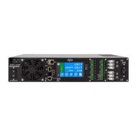
Alpha FXM HP 1100
User Manuals: EnerSys Alpha FXM HP 1100 Power Supply
Manuals and User Guides for EnerSys Alpha FXM HP 1100 Power Supply. We have
1
EnerSys Alpha FXM HP 1100 Power Supply manual available for free PDF download: Technical Manual
EnerSys Alpha FXM HP 1100 Technical Manual (150 pages)
Brand:
EnerSys
| Category:
UPS
| Size: 11 MB
Table of Contents
Table of Contents
5
1 Safety
13
Safety Wording
13
General Warning and Cautions
13
Electrical Safety
13
Battery Safety
14
2 Introduction
15
Scope of the Manual
15
Product Overview
15
About Battery Backup Systems
15
About the Alpha FXM HP
15
Peripherals
16
Alpha Cordex™ HP Digital Controller
16
3 Fxm Hp - Specifications
17
Table 1: Specifications: FXM HP 650, 1100, 2000
17
FXM HP - AVR Transition
20
Table 2: AVR Transition: FXM HP 2000 - 120V
20
Table 3: AVR Transition: FXM HP 650, 1100 - 120V
21
Table 4: AVR Transition: FXM HP 650, 1100, 2000 - 230V
22
4 Features
23
Front Panel
23
Figure 1: FXM HP 650
23
Figure 2: FXM HP 1100/2000
23
Feature Description
24
Table 5: Feature Description
24
Dry Contact Description
25
Figure 3: Dry Contact Overview
25
Table 6: C1 to C5 Dry Contacts
25
Figure 4: User Input Layout
26
Figure 5: Contact Layout (De-Energized Shown, Factory Default for C6)
26
Table 7: C7 to C8 Optically Isolated User Inputs
26
Figure 6: ATS Layout
27
5 Inspection
29
Check for Damage
29
Packing Materials
29
Returns for Service
29
Figure 7: Packing Materials and Environmental Codes
29
6 Installation
31
Tools Required
31
Mounting the Alpha FXM HP
31
Table 8: FXM HP Part Numbers
32
Rotating the Control Panel
34
Replacing the Fan
36
Wiring the External Batteries
37
Wiring the Alpha FXM HP
39
UATS and (UGTS) Option
39
7 Operating the Alpha Fxm Hp
41
Switching the Alpha FXM HP on and off
41
Switch off Procedure
41
Switch on Procedure (LINE Mode)
41
Switching the Alpha FXM HP from Line Mode to Inverter Mode
41
Switching the Alpha FXM HP from Inverter Mode to Line Mode
42
8 Getting Started
43
Navigating the FXM HP User Interface
43
Logging in to the Controller
43
Controller Menu Map
44
Figure 8: Menu Structure
45
Overview of the LCD Interface
46
Figure 9: FXM HP Controller Dashboard
46
Figure 10: Maintenance Page
47
Figure 11: System Maintenance Page
47
Figure 12: LCD Menus
48
Figure 13: Controller Status
49
Figure 14: Time and Date
49
Figure 15: Timezone
50
Figure 16: Network Time Server
50
Figure 17: Synchronize Time
51
Figure 18: System Shortcuts
51
Figure 19: Status
52
Figure 20: AC Input
52
Figure 21: AC Output
52
Figure 22: Battery
53
Figure 23: Battery Test
53
Figure 24: Inverter Control
54
Figure 25: AC Shutdown
54
Figure 26: Counters
55
Figure 27: Keep Alive Status
55
Figure 28: External Fan
55
Figure 29: User Inputs Status
56
Figure 30: User Inputs Configuration
56
Figure 31: User Alarms
57
Figure 32: Relays
57
Figure 33: Relays Status
57
Figure 34: Relays Configuration
58
Overview of the Web Interface
59
Figure 36: Events Logs
59
Figure 37: Dashboard Overview on Web Interface
60
Figure 38: Main Dashboard Tables
61
Figure 39: Table Icons
62
Figure 40: Web Interface Table Features
63
Figure 41: Controller Menu
63
Figure 42: System Wizards
64
Figure 43: Controller with no System Configured
65
Figure 44: Systems Data Tiles
65
Figure 45: System Menu
65
Figure 46: Modules Menu
67
Figure 47: Alarms Menu
67
Email Notification
68
Figure 48: Logs Menu
68
Figure 49: Default Ports: SMTP Client and Server
68
Table 9: Email Notification Features
69
Table 10: Email Configuration
70
Setting up SNMP Communication
71
Configuring IP Address to Receive Notifications
71
Figure 50: Default Ports: SNMP Manager and Agent
71
Figure 51: SNMP Destination Page
72
Figure 52: Destination 1 more Information Page
72
9 Fxm Hp Systems
73
Guidelines for Setting up the FXM HP System
73
The System Mode
73
Figure 53: System Mode
74
Table 11: FXM HP Operating Mode
74
FXM HP System Functions
75
Modules, Inventory and System Functions
75
Battery Charging
75
Battery Temperature Compensation
76
Figure 54: Three-Stage Charging Cycle
76
Battery Test
77
Figure 55: Temperature Compensation Voltage Graph
77
Battery Runtime and Health Estimation
78
AC Output
79
Inverter Control
79
Load Shedding Relays
80
Table 12: Inverter Control Configuration Table
80
Table 13: the Load Shedding Relays Configuration Table
80
External Fan
81
Keep Alive
81
Table 14: External Fan Configuration Table
81
Table 15: Keep Alive Configuration Table
82
Creating a FXM HP System Manually
83
Quick Reference for Configuring a FXM HP System
83
Figure 35: Load Shedding Relays
84
Figure 56: Quick Reference for Configuring a FXM System
84
FXM HP - Default Values
85
Table 16: FXM HP - Default Values
85
Creating a FXM HP System
88
Configure the Battery Parameters
93
Configure the Battery Temperature Sensors
93
Configure the Charging System Function
94
Configure the Elevated Absorption Charging System
95
Configure the Temperature Compensation System Function
95
Running Battery Tests
95
Configure Battery Runtime and Health Estimation
97
Configure AC Shutdown
97
Configure External Fan
98
Configure Keep Alive
99
Configure Soft Shutdown
99
Configure SNMP UPS Management Information Base
99
Configure Relays
99
Configure Power Outage Alarm
101
10 Maintaining the Controller
103
Ethernet Communications
103
Connecting Via the Web
104
Working with Alarms
104
Active Alarms
104
Alarm Cut-Off
105
Alarm Activation Delay at Startup
105
Alarm Summary Relays
105
Creating User Alarms
107
Controller Maintenance
108
Resetting the Controller
108
Resetting Via the LCD
109
Changing the Time and Date
109
Changing the Default Login Language
110
Changing User Interface Strings
111
Changing the Web Session Language
112
Changing the System Status Bar
113
Changing the Dashboard Values
114
Data Sharing
114
Replacing the Controller Battery
116
Working with Logs
117
Event and Alert Logs
117
Figure 57: Events and Alerts Log
117
Battery Log
118
Figure 58: Battery Log on the LCD
118
Power Outage Log
119
Datalogs
119
Figure 59: Battery Log on the Web
119
Figure 60: Battery Log in Excel
119
Figure 61: Datalogs Table
119
Figure 62: Datalog Window: Status, Signals, Configuration and Preview Chart
120
Performance Logs
123
File Maintenance
123
Figure 63: CPU Memory in Use Performance Log
123
File Maintenance Via the LCD
124
File Preferences
124
Upgrading the Controller Software
126
Exporting Configuration
127
Importing Configuration
128
Exporting Diagnostic Information
130
Exporting Inventory
130
User Account Maintenance
131
Setting up Users and Permissions
131
Editing User Permissions
131
Enabling New Users
132
Disabling Users
134
Changing the Default Password - LCD
135
Changing the Default Password - Web
136
Remote Configuration Lockout
137
Module Firmware Upgrades
137
Module Firmware Upgrade
137
Uploading a Firmware File
138
Figure 64: Module Upgrade Page - Web
138
Figure 65: Module Upgrade - LCD
138
Figure 66: Firmware Files Table
139
Figure 67: Upload File Dialog
139
Selecting the File to Upgrade
140
Figure 68: Ready to Start Upgrade
140
Upgrading the Module
141
Figure 69: Upgrade in Progress
141
Figure 70: Upgrade Succeeded
142
11 Appendixa - Triggers
143
12 Warranty and Service Information
145
Technical Support
145
Warranty Statement
145
Product Warranty
145
Battery Warranty
145
Warranty Claims
145
Service Information
145
13 Certification
147
Advertisement
Advertisement
Related Products
EnerSys Alpha FXM HP 650
EnerSys Alpha FXM HP 2000
EnerSys Alpha Cordex HP 3.0kW
EnerSys PowerSafe HB30
EnerSys HAW-24-2.6
EnerSys HAW-48-36.5
EnerSys HAW-48-39.1
EnerSys Hawker EvoRail
EnerSys Hawker Evolution
EnerSys HAWKER PerfectRail DS
EnerSys Categories
Camera Accessories
Battery Pack
Battery Charger
Power Supply
Industrial Equipment
More EnerSys Manuals
Login
Sign In
OR
Sign in with Facebook
Sign in with Google
Upload manual
Upload from disk
Upload from URL