Sign In
Upload
Manuals
Brands
Endress+Hauser Manuals
Measuring Instruments
Proline t-mass 65
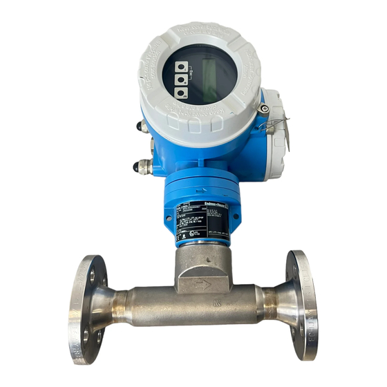
Endress+Hauser Proline t-mass 65 Manuals
Manuals and User Guides for Endress+Hauser Proline t-mass 65. We have
11
Endress+Hauser Proline t-mass 65 manuals available for free PDF download: Operating Instructions Manual, Brief Operating Instructions
Endress+Hauser Proline t-mass 65 Operating Instructions Manual (122 pages)
Thermal Mass Flow Measuring System for PROFIBUS DP/PA
Brand:
Endress+Hauser
| Category:
Measuring Instruments
| Size: 2.97 MB
Table of Contents
Operating Instructions
1
Table of Contents
3
1 Safety Instructions
5
Designated Use
5
Installation, Commissioning and Operation
5
Operational Safety
6
Return
6
Notes on Safety Conventions and Icons
6
2 Identification
7
Device Designation
7
Nameplate of the Transmitter
7
Nameplate of the Sensor
8
Nameplate for Connections
9
Certificates and Approvals
10
Registered Trademarks
10
3 Installation
11
Incoming Acceptance, Transport and Storage
11
Incoming Acceptance
11
Transport
11
Storage
11
Installation Conditions
12
Dimensions
12
System Pressure and Pulsating Flow
12
Pipework Requirements
13
Orientation
14
Inlet and Outlet Runs
15
Heating
18
Thermal Insulation
18
Vibrations
18
Installation Instructions
19
Mounting the Insertion Sensor
19
Removing the Insertion Sensor
22
Mounting the Flanged Sensor
22
Turning the Transmitter Housing
23
Turning the Local Display
23
Transmitter Housing
24
Post-Installation Check
26
4 Wiring
27
Cable Specifications
27
PROFIBUS DP Cable Specifications
27
Shielding and Grounding
28
Connecting the Remote Version
29
Connecting Connecting Cable for Sensor/Transmitter
29
Cable Specification, Connecting Cable
29
Connecting the Measuring Unit
30
Terminal Assignment
30
Transmitter Connection
30
PROFIBUS DP Connection Diagram
31
PROFIBUS PA Connection Diagram
32
Degree of Protection
34
Post-Connection Check
35
Operation
36
Quick Operation Guide
36
Local Display
37
Display and Operating Elements
37
Icons
37
Brief Operating Instructions to the Function Matrix
38
General Notes
39
Enabling the Programming Mode
39
Disabling the Programming Mode
39
Error Messages
40
Type of Error
40
Error Message Type
40
Operating Options
41
Fieldcare
41
Operating Program "SIMATIC PDM" (Siemens)
41
Current Device Description Files
41
PROFIBUS DP Hardware Settings
43
Configuring the Write Protection
43
Configuring the Device Address
44
Configuring the Terminating Resistors
45
PROFIBUS PA Hardware Settings
46
Configuring the Write Protection
46
Configuring the Device Address
47
6 Commissioning
48
Function Check
48
Switching on the Measuring Device
48
Quick Setup
48
Quick Setup "Commissioning
49
Quick Setup "Sensor
51
Gas" Quick Setup Menu
52
Pressure" Quick Setup Menu
54
Heat Flow" Quick Setup Menu
55
Quick Setup "Communication
57
Data Backup/Transmission
58
Commissioning the PROFIBUS Interface
59
PROFIBUS DP/PA Commissioning
59
PROFIBUS DP/PA System Integration
61
Device Master File (GSD File)
61
Example for Selecting the GSD File
63
Maximum Number of Writes
63
PROFIBUS DP Cyclic Data Transmission
64
Block Model
64
Modules for Cyclic Data Transmission
65
Description of the Modules
66
Configuration Examples with Simatic S7 HW-Konfig
71
PROFIBUS PA Cyclic Data Transmission
73
Block Model
73
Modules for Cyclic Data Transmission
74
Description of the Modules
75
Configuration Examples with Simatic S7 HW-Konfig
80
PROFIBUS DP/PA Acyclic Data Transmission
82
Master Class 2 Acyclic (MS2AC)
82
Master Class 1 Acyclic (MS1AC)
82
Adjustment
83
Zero Point Adjustment
83
Data Storage Device (Historom)
84
Historom/S-DAT (Sensor-DAT)
84
Historom/T-DAT (Transmitter-DAT)
84
7 Maintenance
85
External Cleaning
85
Pipe Cleaning
85
Transducer Cleaning
85
Replacing Seals
86
In-Situ Calibration
86
Recalibration
86
8 Accessories
87
Device-Specific Accessories
87
Measuring Principle-Specific Accessories
87
Service-Specific Accessories
88
Advertisement
Endress+Hauser Proline t-mass 65 Operating Instructions Manual (100 pages)
Thermal Mass Flow Measuring System
Brand:
Endress+Hauser
| Category:
Measuring Instruments
| Size: 3.1 MB
Table of Contents
Table of Contents
3
Safety Instructions
5
Designated Use
5
Installation, Commissioning and Operation
5
Operational Safety
6
Return
6
Notes on Safety Conventions and Icons
6
Identification
7
Device Designation
7
Nameplate of the Transmitter
7
Nameplate of the Sensor
8
Nameplate for Connections
9
Certificates and Approvals
10
Registered Trademarks
10
Installation
11
Incoming Acceptance, Transport and Storage
11
Incoming Acceptance
11
Transport
11
Storage
11
Installation Conditions
12
Dimensions
12
Pipework Requirements
12
Orientation
13
Inlet and Outlet Runs
14
Outlet Runs with Pressure
16
Measuring Points
16
Perforated Plate Flow Conditioner
16
The Flanged Version
17
The Insertion Version
17
Insertion Depth for the Insertion Version
18
Low Pressure Retractable Process Connection
19
System Pressure
22
External Pressure Compensation
23
Temperature Range
23
Heating
23
Thermal Insulation
24
Vibrations
24
Installation Instructions
25
Turning the Transmitter Housing
25
Installing the Wall-Mount
25
Transmitter Housing
25
Turning the Local Display
27
Post-Installation Check
28
Wiring
29
Cable Specification MODBUS RS485
29
Cable Type
29
Shielding and Grounding
30
Connecting the Remote Version
31
Connecting Connecting
31
Cable for Sensor/Transmitter
31
Cable Specification, Connecting Cable
32
Connecting the Measuring Unit
32
Terminal Assignment
32
Transmitter Connection
32
MODBUS RS485 Connection Diagram
33
Degree of Protection
34
Post-Connection Check
35
Operation
36
Quick Operation Guide
36
Local Display
37
Display and Operating Elements
37
Icons
37
Brief Operating Instructions to the Function Matrix
38
General Notes
39
Enabling the Programming Mode
39
Disabling the Programming Mode
39
Error Messages
40
Type of Error
40
Error Message Type
40
MODBUS RS485 Communication
41
MODBUS RS485 Technology
41
MODBUS Telegram
43
MODBUS Function Codes
44
Maximum Number of Writes
45
MODBUS Register Addresses
45
MODBUS Error Messages
48
MODBUS Auto-Scan Buffer
48
Operating Options
53
Tof Tool - Fieldtool Package
53
Fieldcare
53
Device Drivers for Operating Programs
53
Hardware Settings
54
Hardware Write Protection
54
Switching on and off
54
Configuring the Device Address
55
Configuring the Terminating Resistors
56
Commissioning
57
Function Check
57
Switching on the Measuring Device
57
Quick Setup
58
Commissioning
58
Communication
60
Data Back-Up with T-DAT SAVE/LOAD Function
62
Adjustment
63
Zero Point Adjustment
63
Data Storage Device (Historom)
64
Historom/S-DAT
64
(Sensor-DAT)
64
Historom/T-DAT
64
(Transmitter-DAT)
64
Maintenance
65
External Cleaning
65
Pipe Cleaning
65
Transducer Cleaning
65
Replacing Seals
65
In-Situ Calibration
65
Accessories
66
Device-Specific Accessories
66
Measuring Principle-Specific Accessories
66
Service-Specific Accessories
67
Trouble-Shooting
68
Trouble-Shooting Instructions
68
System Error Messages
69
List of System Error Messages
70
Process Error Messages
74
List of Process Error Messages
74
Process Errors Without Messages
75
Response of Totalizers and MODBUS
76
Communication to Errors
76
Spare Parts
77
Endress+Hauser Proline t-mass 65 Operating Instructions Manual (106 pages)
MODBUS RS485, Thermal Mass Flow Measuring System
Brand:
Endress+Hauser
| Category:
Measuring Instruments
| Size: 2.7 MB
Table of Contents
Operating Instructions
1
Table of Contents
3
1 Safety Instructions
5
Designated Use
5
Installation, Commissioning and Operation
5
Operational Safety
6
Return
6
Notes on Safety Conventions and Icons
6
2 Identification
7
Device Designation
7
Nameplate of the Transmitter
7
Nameplate of the Sensor
8
Nameplate for Connections
9
Certificates and Approvals
10
Registered Trademarks
10
3 Installation
11
Incoming Acceptance, Transport and Storage
11
Incoming Acceptance
11
Transport
11
Storage
11
Installation Conditions
12
Dimensions
12
System Pressure and Pulsating Flow
12
Pipework Requirements
13
Orientation
14
Inlet and Outlet Runs
15
Heating
18
Thermal Insulation
18
Vibrations
18
Installation Instructions
19
Mounting the Insertion Sensor
19
Removing the Insertion Sensor
22
Mounting the Flanged Sensor
22
Turning the Transmitter Housing
23
Turning the Local Display
23
Transmitter Housing
24
Post-Installation Check
26
4 Wiring
27
Cable Specification MODBUS RS485
27
Cable Type
27
Shielding and Grounding
27
Connecting the Remote Version
28
Connecting Connecting Cable for Sensor/Transmitter
28
Cable Specification, Connecting Cable
29
Connecting the Measuring Unit
30
Terminal Assignment
30
Transmitter Connection
30
MODBUS RS485 Connection Diagram
31
Degree of Protection
32
Post-Connection Check
33
Operation
34
Quick Operation Guide
34
Display and Operating Elements
35
Brief Operating Instructions to the Function Matrix
36
General Notes
37
Enabling the Programming Mode
37
Disabling the Programming Mode
37
Error Messages
38
Type of Error
38
Error Message Type
38
MODBUS RS485 Communication
39
MODBUS RS485 Technology
39
MODBUS Telegram
41
MODBUS Function Codes
42
Maximum Number of Writes
43
MODBUS Register Addresses
43
MODBUS Error Messages
46
MODBUS Auto-Scan Buffer
46
Operating Options
51
Fieldcare
51
Device Drivers for Operating Programs
51
Hardware Settings
52
Hardware Write Protection
52
Switching on and off
52
Configuring the Device Address
53
Configuring the Terminating Resistors
54
6 Commissioning
55
Function Check
55
Switching on the Measuring Device
55
Quick Setup
56
Quick Setup "Commissioning
56
Quick Setup "Sensor
58
Gas" Quick Setup Menu
59
Pressure" Quick Setup Menu
61
Heat Flow" Quick Setup Menu
62
Quick Setup "Communication
64
Data Backup/Transmission
66
Adjustment
67
Zero Point Adjustment
67
Data Storage Device (Historom)
68
Historom/S-DAT (Sensor-DAT)
68
Historom/T-DAT (Transmitter-DAT)
68
7 Maintenance
69
External Cleaning
69
Pipe Cleaning
69
Transducer Cleaning
69
Replacing Seals
70
In-Situ Calibration
70
Recalibration
70
8 Accessories
71
Device-Specific Accessories
71
Measuring Principle-Specific Accessories
71
Service-Specific Accessories
72
9 Trouble-Shooting
73
Trouble-Shooting Instructions
73
System Error Messages
75
Process Error Messages
78
Process Errors Without Messages
79
Response of Totalizers and MODBUS Communication to
81
Errors
81
Spare Parts
82
Removing and Installing Printed Circuit Boards
83
Replacing the Device Fuse
88
Return
89
Disposal
89
Software History
90
Advertisement
Endress+Hauser Proline t-mass 65 Operating Instructions Manual (102 pages)
FOUNDATION Fieldbus Thermal Mass Flow Measuring System
Brand:
Endress+Hauser
| Category:
Measuring Instruments
| Size: 2.23 MB
Table of Contents
Operating Instructions
1
Table of Contents
3
1 Safety Instructions
5
Designated Use
5
Installation, Commissioning and Operation
5
Operational Safety
6
Return
6
Notes on Safety Conventions and Icons
6
2 Identification
7
Device Designation
7
Nameplate of the Transmitter
7
Nameplate of the Sensor
8
Nameplate for Connections
9
Certificates and Approvals
10
FOUNDATION Fieldbus Device Certification
10
Registered Trademarks
10
3 Installation
11
Incoming Acceptance, Transport and Storage
11
Incoming Acceptance
11
Transport
11
Storage
11
Installation Conditions
12
Dimensions
12
System Pressure and Pulsating Flow
12
Pipework Requirements
13
Orientation
14
Inlet and Outlet Runs
15
Heating
18
Thermal Insulation
18
Vibrations
18
Installation Instructions
19
Mounting the Insertion Sensor
19
Removing the Insertion Sensor
22
Mounting the Flanged Sensor
22
Turning the Transmitter Housing
23
Turning the Local Display
23
Transmitter Housing
24
Post-Installation Check
26
4 Wiring
27
FOUNDATION Fieldbus Cable Specification
27
Cable Type
27
Maximum Overall Cable Length
28
Maximum Spur Length
28
Number of Field Devices
28
Shielding and Grounding
28
Bus Termination
29
Further Information
29
Connecting the Remote Version
30
Connecting Connecting Cable for Sensor
30
Transmitter
30
Cable Specification, Connecting Cable
30
Connecting the Measuring Unit
31
Transmitter Connection
31
Terminal Assignment
34
Degree of Protection
34
Post-Connection Check
35
5 Operation
36
Quick Operation Guide
36
Display and Operating Elements
37
Brief Operating Instructions to the Function Matrix
38
General Notes
39
Enabling the Programming Mode
39
Disabling the Programming Mode
39
Error Messages
40
Type of Error
40
Error Message Type
40
Communication
41
Fieldcare
41
Operating Via FOUNDATION Fieldbus
41
Configuration Programs
41
Current Device Description Files
42
FOUNDATION Fieldbus Hardware Settings
43
Switching Hardware Write Protection on and off
43
6 Commissioning
44
Function Check
44
Switching on the Measuring Device
44
Commissioning with FOUNDATION Fieldbus
45
Commissioning
45
Gas Compensation Input
50
Quick Setup
52
Quick Setup "Commissioning
52
Quick Setup "Sensor
54
Gas" Quick Setup Menu
55
Pressure" Quick Setup Menu
57
Heat Flow" Quick Setup Menu
58
Data Backup/Transmission
60
Adjustment
61
Zero Point Adjustment
61
Data Storage Device (Historom)
62
Historom/S-DAT (Sensor-DAT)
62
Historom/T-DAT (Transmitter-DAT)
62
7 Maintenance
63
External Cleaning
63
Pipe Cleaning
63
Transducer Cleaning
63
Replacing Seals
64
In-Situ Calibration
64
Recalibration
64
Accessories
65
Device-Specific Accessories
65
Measuring Principle-Specific Accessories
65
Service-Specific Accessories
66
9 Trouble-Shooting
67
Troubleshooting Instructions
67
System/Process Error Messages
71
List of System Error Messages
72
List of Process Error Messages
77
Process Errors Without Messages
77
Spare Parts
79
Removing and Installing Printed
80
Circuit Boards
80
Replacing the Device Fuse
85
Return
86
Disposal
86
Software History
86
Endress+Hauser Proline t-mass 65 Operating Instructions Manual (102 pages)
Thermal Mass Flow Measuring System
Brand:
Endress+Hauser
| Category:
Measuring Instruments
| Size: 2.58 MB
Table of Contents
Operating Instructions
1
Table of Contents
3
1 Safety Instructions
5
Designated Use
5
Installation, Commissioning and Operation
5
Operational Safety
6
Return
6
Notes on Safety Conventions and Icons
6
2 Identification
7
Device Designation
7
Nameplate of the Transmitter
7
Nameplate of the Sensor
8
Nameplate for Connections
9
Certificates and Approvals
10
Registered Trademarks
10
3 Installation
11
Incoming Acceptance, Transport and Storage
11
Incoming Acceptance
11
Transport
11
Storage
11
Installation Conditions
12
Dimensions
12
System Pressure and Pulsating Flow
12
Pipework Requirements
13
Orientation
14
Inlet and Outlet Runs
15
Heating
18
Thermal Insulation
18
Vibrations
18
Installation Instructions
19
Mounting the Insertion Sensor
19
Removing the Insertion Sensor
22
Mounting the Flanged Sensor
22
Turning the Transmitter Housing
23
Turning the Local Display
23
Transmitter Housing
24
3.3.6 Installing the Wall-Mount
24
Post-Installation Check
26
4 Wiring
27
Connecting the Remote Version
27
Connecting Connecting Cable for Sensor
27
Transmitter
27
Cable Specification, Connecting Cable
28
Connecting the Measuring Unit
29
Transmitter Connection
29
Terminal Assignment
31
HART Connection
32
Degree of Protection
33
Post-Connection Check
33
5 Operation
34
Display and Operating Elements
34
Brief Operating Instructions to the Function Matrix
35
General Notes
36
Enabling the Programming Mode
36
Disabling the Programming Mode
36
Error Messages
37
Type of Error
37
Error Message Type
37
Communication
38
Operating Options
38
Current Device Description Files
39
Device and Process Variables
39
HART Commands
40
Device Status / Error Messages
45
Switching HART Write Protection on and off
48
6 Commissioning
49
Function Check
49
Switching on the Measuring Device
49
Quick Setup
49
Quick Setup "Commissioning
50
Quick Setup "Sensor
52
Gas" Quick Setup Menu
53
Pressure" Quick Setup Menu
55
Heat Flow" Quick Setup Menu
56
Data Backup/Transmission
58
External Pressure Compensation Input
59
Gas Compensation Input
59
Configuration
61
One Current Output: Active/Passive
61
Two Current Outputs: Active/Passive
62
Current Input: Active/Passive
63
Relay Contacts: Normally Closed
64
Normally Open
64
Adjustment
65
Zero Point Adjustment
65
Proline T-Mass
65
Data Storage Device (Historom)
66
Historom/S-DAT (Sensor-DAT)
66
Historom/T-DAT (Transmitter-DAT)
66
7 Maintenance
67
External Cleaning
67
Pipe Cleaning
67
Transducer Cleaning
67
Replacing Seals
68
In-Situ Calibration
68
Recalibration
68
8 Accessories
69
Device-Specific Accessories
69
Measuring Principle-Specific Accessories
69
Communication-Specific Accessories
70
Service-Specific Accessories
70
9 Trouble-Shooting
71
Trouble-Shooting Instructions
71
System Error Messages
72
Process Error Messages
76
Process Errors Without Messages
76
Failure Mode of Outputs
78
Spare Parts
79
Removing and Installing Printed
80
Circuit Boards
80
Replacing the Device Fuse
85
Return
86
Disposal
86
Software History
87
Endress+Hauser Proline t-mass 65 Operating Instructions Manual (98 pages)
Thermal Mass Flow Measuring System
Brand:
Endress+Hauser
| Category:
Measuring Instruments
| Size: 3.23 MB
Table of Contents
Table of Contents
3
Safety Instructions
5
Designated Use
5
Installation, Commissioning and Operation
5
Operational Safety
5
Return
6
Notes on Safety Conventions and Icons
6
Identification
7
Device Designation
7
Nameplate of the Transmitter
7
Nameplate of the Sensor
8
Nameplate for Connections
9
Certificates and Approvals
9
Registered Trademarks
10
Installation
11
Incoming Acceptance, Transport and Storage
11
Incoming Acceptance
11
Transport
11
Storage
11
Installation Conditions
12
Dimensions
12
Pipework Requirements
12
Orientation
13
Inlet and Outlet Runs
14
Outlet Runs with Pressure Measuring Points
16
Perforated Plate Flow Conditioner
16
Flow Direction Alignment for the Flanged
18
Version
18
Flow Direction Alignment for the Insertion
18
Insertion Depth for the Insertion Version
19
Low Pressure Retractable Process
20
Connection
20
System Pressure
23
Pressure Compensation Input
24
Temperature Range
24
Heating
24
Thermal Insulation
25
Vibrations
25
Installation Instructions
26
Turning the Transmitter Housing
26
Installing the Wall-Mount Transmitter
26
Housing
26
Turning the Local Display
28
Post-Installation Check
29
Wiring
30
Connecting the Remote Version
30
Connecting Connecting Cable for Sensor
30
Transmitter
30
Cable Specification, Connecting Cable
31
Connecting the Measuring Unit
31
Transmitter Connection
31
Terminal Assignment
33
HART Connection
34
Degree of Protection
35
Post-Connection Check
35
Operation
36
Display and Operating Elements
36
Brief Operating Instructions to the Function Matrix
37
General Notes
38
Enabling the Programming Mode
38
Disabling the Programming Mode
38
Error Messages
39
Type of Error
39
Error Message Type
39
Communication
40
Operating Options
40
Current Device Description Files
41
Device and Process Variables
42
Universal / Common Practice HART
43
Commands
44
Device Status / Error Messages
48
Switching HART Write Protection on and off
51
Commissioning
53
Function Check
53
Switching on the Measuring Device
53
Quick Setup
54
Quick Setup "Commissioning
54
Data Back-Up with "T-DAT SAVE/LOAD
57
Configuration
58
One Current Output: Active/Passive
58
Two Current Outputs: Active/Passive
59
Current Input: Active/Passive
60
Relay Contacts: Normally Closed
61
Normally Open
61
Adjustment
62
Zero Point Adjustment
62
Data Storage Device (Historom)
63
Historom/S-DAT (Sensor-DAT)
63
Historom/T-DAT (Transmitter-DAT)
63
Maintenance
64
External Cleaning
64
Pipe Cleaning
64
Transducer Cleaning
64
Replacing Seals
64
In-Situ Calibration
64
Accessories
65
Device-Specific Accessories
65
Measuring Principle-Specific Accessories
65
Communication-Specific Accessories
65
Service-Specific Accessories
66
Trouble-Shooting
67
Trouble-Shooting Instructions
67
System Error Messages
68
Process Error Messages
72
Process Errors Without Messages
72
Process Error Messages
74
Spare Parts
75
Removing and Installing Printed Circuit
76
Boards
76
Replacing the Device Fuse
81
Endress+Hauser Proline t-mass 65 Operating Instructions Manual (107 pages)
Modbus RS485 Thermal Mass Flowmeter
Brand:
Endress+Hauser
| Category:
Industrial Equipment
| Size: 2.26 MB
Table of Contents
Table of Contents
2
1 Document Information
3
Document Conventions
3
2 Safety Instructions
5
Designated Use
5
Installation, Commissioning and Operation
5
Operational Safety
6
Return
6
Product Safety
6
3 Identification
7
Device Designation
7
Certificates and Approvals
10
Registered Trademarks
10
4 Installation
11
Incoming Acceptance, Transport and Storage
11
Installation Conditions
12
Installation
19
Post-Installation Check
27
5 Electrical Connection
28
Cable Specification Modbus RS485
28
Connecting the Remote Version
29
Connecting the Measuring Unit
30
Degree of Protection
32
Post-Connection Check
33
6 Operation
34
Quick Operation Guide
34
Display and Operating Elements
35
Brief Operating Instructions for the Function Matrix
36
Error Messages
38
Modbus RS485 Communication
39
Operating Options
51
Hardware Settings
52
7 Commissioning
55
Function Check
55
Switching on the Measuring Device
55
Quick Setup
55
Adjustment
69
Data Storage Device (Historom)
70
8 Maintenance
71
External Cleaning
71
Pipe Cleaning
71
Sensor Cleaning
71
Replacing Seals
72
In-Situ Calibration
72
Recalibration
72
9 Accessories
73
Device-Specific Accessories
73
Service-Specific Accessories
73
10 Trouble-Shooting
75
Trouble-Shooting Instructions
75
System Error Messages
77
Process Error Messages
80
Process Errors Without Messages
80
Response of Totalizers and Modbus Communication
83
To Errors
83
Spare Parts
84
Return
91
Disposal
91
Software History
92
Endress+Hauser Proline t-mass 65 Operating Instructions Manual (103 pages)
Thermal mass flowmeter
Brand:
Endress+Hauser
| Category:
Measuring Instruments
| Size: 8.74 MB
Table of Contents
Table of Contents
2
1 Document Information
3
Document Conventions
3
2 Safety Instructions
5
Designated Use
5
Installation, Commissioning and Operation
5
Operational Safety
6
Return
6
Product Safety
6
3 Identification
7
Device Designation
7
Certificates and Approvals
10
Registered Trademarks
10
4 Installation
11
Incoming Acceptance, Transport and Storage
11
Installation Conditions
12
Installation
19
Post-Installation Check
27
5 Electrical Connection
28
Connecting the Remote Version
28
Connecting the Measuring Unit
30
Degree of Protection
33
Post-Connection Check
34
6 Operation
35
Display and Operating Elements
35
Brief Operating Instructions for the Function Matrix
36
General Notes
37
Error Messages
38
Communication
39
7 Commissioning
50
Function Check
50
Switching on the Measuring Device
50
Quick Setup
50
Configuration
61
Adjustment
65
Data Storage Device (Historom)
66
8 Maintenance
67
External Cleaning
67
Pipe Cleaning
67
Sensor Cleaning
67
Replacing Seals
68
In-Situ Calibration
68
Recalibration
68
9 Accessories
69
Device-Specific Accessories
69
Communication-Specific Accessories
69
Service-Specific Accessories
70
10 Trouble-Shooting
71
Trouble-Shooting Instructions
71
System Error Messages
72
Process Error Messages
76
Process Errors Without Messages
76
Response of Outputs to Errors
78
Spare Parts
79
Return
86
Disposal
86
Software History
87
Endress+Hauser Proline t-mass 65 Operating Instructions Manual (32 pages)
Thermal mass flowmeter
Brand:
Endress+Hauser
| Category:
Measuring Instruments
| Size: 2.52 MB
Table of Contents
Table of Contents
2
1 Document Information
3
Document Conventions
3
2 Basic Safety Instructions
5
Requirements for Personnel
5
Designated Use
5
Occupational Safety
6
Operational Safety
7
Product Safety
7
3 Installation
8
Transporting to the Measuring Point
8
Installation Conditions
8
Installation
15
Post-Installation Check
17
4 Wiring
18
Connecting the Various Housing Types
19
Degree of Protection
20
Post-Connection Check
20
5 Hardware Settings
21
Device Address
21
Terminating Resistors
23
6 Commissioning
24
Switching on the Measuring Device
24
Operation
25
Navigating Within the Function Matrix
26
Calling the Commission Quick Setup
27
Software Settings
28
Troubleshooting
29
Endress+Hauser Proline t-mass 65 Brief Operating Instructions (28 pages)
Thermal Mass Flow Measuring System
Brand:
Endress+Hauser
| Category:
Measuring Instruments
| Size: 2.34 MB
Table of Contents
Table of Contents
2
Safety Instructions
3
Designated Use
3
Installation, Commissioning and Operation
3
Operational Safety
3
Safety Conventions
4
Installation
5
Transporting to the Measuring Point
5
Installation Conditions
5
Installation Instructions
11
Post-Installation Check
14
Wiring
15
Connecting the Various Housing Types
16
Degree of Protection
17
Post-Connection Check
17
Hardware Settings
18
Device Address
18
Terminating Resistors
20
Commissioning
21
Switching on the Measuring Device
21
Operation
22
Navigating Within the Function Matrix
23
Calling the Commissioning Quick Setup
24
Software Settings
25
Troubleshooting
26
Endress+Hauser Proline t-mass 65 Brief Operating Instructions (28 pages)
Thermal Mass Flow Measuring System
Brand:
Endress+Hauser
| Category:
Measuring Instruments
| Size: 1.04 MB
Table of Contents
Table of Contents
2
Safety Instructions
3
Designated Use
3
Installation, Commissioning and Operation
3
Operational Safety
3
Safety Conventions
4
Installation
5
Transporting to the Measuring Point
5
Installation Conditions
5
Installation Instructions
12
Post-Installation Check
14
Wiring
15
Connecting the Various Housing Types
16
Degree of Protection
17
Post-Connection Check
17
Hardware Settings
18
Device Address
18
Terminating Resistors
20
Commissioning
21
Switching on the Measuring Device
21
Operation
22
Navigating Within the Function Matrix
23
Calling the Commission Quick Setup
24
Software Settings
25
Troubleshooting
26
Advertisement
Related Products
Endress+Hauser Prolinet-mass F
Endress+Hauser Proline t-mass I
Endress+Hauser Proline t-mass 65 PROFIBUS DP
Endress+Hauser Proline t-mass 65 PROFIBUS DA
Endress+Hauser Proline t-mass 65 MODBUS RS485
Endress+Hauser Proline Promass 84F
Endress+Hauser Proline Promass 84M
Endress+Hauser Proline Prosonic Flow 92F Series
Endress+Hauser Proline 10
Endress+Hauser Proline Promass H 300 PROFINET
Endress+Hauser Categories
Measuring Instruments
Transmitter
Radar
Switch
Accessories
More Endress+Hauser Manuals
Login
Sign In
OR
Sign in with Facebook
Sign in with Google
Upload manual
Upload from disk
Upload from URL