Sign In
Upload
Manuals
Brands
Endress+Hauser Manuals
Measuring Instruments
Proline Promag W 400 HART
Endress+Hauser Proline Promag W 400 HART Manuals
Manuals and User Guides for Endress+Hauser Proline Promag W 400 HART. We have
2
Endress+Hauser Proline Promag W 400 HART manuals available for free PDF download: Operating Instructions Manual
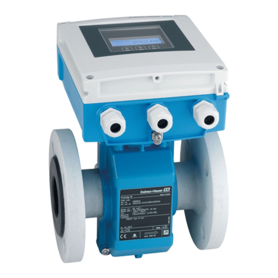
Endress+Hauser Proline Promag W 400 HART Operating Instructions Manual (214 pages)
Electromagnetic flowmeter
Brand:
Endress+Hauser
| Category:
Measuring Instruments
| Size: 6 MB
Table of Contents
Operating Instructions
1
Table of Contents
3
1 Document Information
6
Document Function
6
Symbols Used
6
Safety Symbols
6
Electrical Symbols
6
Tool Symbols
6
Symbols for Certain Types of Information
7
Symbols in Graphics
7
Documentation
7
Information 7
7
Standard Documentation
8
Supplementary Device-Dependent Documentation
8
Registered Trademarks
8
2 Basic Safety Instructions
9
Requirements for the Personnel
9
Designated Use
9
Workplace Safety
10
Operational Safety
10
Product Safety
11
IT Security
11
3 Product Description
12
Product Design
12
4 Incoming Acceptance and Product
13
Identification
13
Incoming Acceptance
13
Product Identification
13
Transmitter Nameplate
14
Sensor Nameplate
15
Symbols on Measuring Device
16
5 Storage and Transport
17
Storage Conditions
17
Transporting the Product
17
Measuring Devices Without Lifting Lugs
17
Measuring Devices with Lifting Lugs
18
Transporting with a Fork Lift
18
Packaging Disposal
18
6 Installation
19
Installation Conditions
19
Mounting Position
19
Requirements from Environment and Process
21
Special Mounting Instructions
23
Mounting the Measuring Device
24
Required Tools
24
Preparing the Measuring Device
24
Mounting the Sensor
24
Mounting the Transmitter of the Remote Version
30
Turning the Transmitter Housing
32
Turning the Display Module
34
Post-Installation Check
35
7 Electrical Connection
36
Connection Conditions
36
Required Tools
36
Requirements for Connecting Cable
36
Terminal Assignment
38
Shielding and Grounding
40
Requirements for the Supply Unit
40
Preparing the Measuring Device
40
Preparing the Connecting Cable for the Remote Version
40
Connecting the Measuring Device
41
Connecting the Remote Version
41
Connecting the Transmitter
43
Ensuring Potential Equalization
44
Special Connection Instructions
46
Ensuring the Degree of Protection
46
Degree of Protection IP66/67, Type 4X Enclosure
46
Degree of Protection IP68, Type 6P Enclosure, with "Cust-Potted" Option
46
Post-Connection Check
46
8 Operation Options
48
Overview of Operation Options
48
Structure and Function of the Operating Menu
49
Structure of the Operating Menu
49
Operating Philosophy
50
Access to the Operating Menu Via the Local Display
51
Operational Display
51
Navigation View
53
Editing View
55
Operating Elements
56
Opening the Context Menu
57
Navigating and Selecting from List
59
Calling the Parameter Directly
59
Calling up Help Text
60
Changing the Parameters
61
User Roles and Related Access Authorization
62
Disabling Write Protection Via Access
62
Code
62
Enabling and Disabling the Keypad Lock
62
Access to the Operating Menu Via the Web Browser
63
Function Range
63
Prerequisites
63
Establishing a Connection
64
Logging on
65
User Interface
65
Disabling the Web Server
66
Logging out
67
Access to the Operating Menu Via the Operating Tool
67
Connecting the Operating Tool
67
Field Xpert SFX350, SFX370
68
Fieldcare
68
AMS Device Manager
69
Simatic Pdm
70
Field Communicator 475
70
9 System Integration
71
Overview of Device Description Files
71
Current Version Data for the Device
71
Operating Tools
71
Measured Variables Via HART Protocol
71
Other Settings
72
Burst Mode Functionality in Accordance with HART 7
72
Specification
72
10 Commissioning
75
Function Check
75
Switching on the Measuring Device
75
Establishing a Connection Via Fieldcare
75
Setting the Operating Language
75
Configuring the Measuring Device
76
Defining the Tag Name
82
Configuring the Status Input
82
Configuring the Current Output
84
Configuring the Pulse/Frequency
85
Switch Output
85
Configuring the Local Display
92
Configuring the Output
94
Conditioning
94
Configuring the Low Flow Cut off
96
Configuring Empty Pipe Detection
98
Configuring the HART Input
99
Advanced Settings
101
Setting the System Units
103
Carrying out a Sensor Adjustment
105
Configuring the Totalizer
105
Carrying out Additional Display Configurations
106
Performing Electrode Cleaning
108
Administration Configuration
109
Configuration Management
109
Function Range of "Configuration Management" Parameter
110
Simulation
111
Protecting Settings from Unauthorized
113
Access
113
Write Protection Via Access Code
113
Write Protection Via Write Protection
114
Switch
114
11 Operation
116
Reading the Device Locking Status
116
Adjusting the Operating Language
116
Configuring the Display
116
Reading Measured Values
116
Process Variables
116
Totalizer
117
Input Values
117
Output Values
118
Adapting the Measuring Device to the Process
119
Conditions
119
Performing a Totalizer Reset
119
Showing Data Logging
120
12 Diagnostics and Troubleshooting
122
General Troubleshooting
122
Diagnostic Information Via Light Emitting
123
Diodes
123
Transmitter
123
Diagnostic Information on Local Display
125
Diagnostic Message
125
Calling up Remedial Measures
127
Diagnostic Information in the Web Browser
128
12.4.1 Diagnostic Options
128
Calling up Remedy Information
128
Diagnostic Information in Fieldcare
129
Diagnostic Options
129
Calling up Remedy Information
130
Adapting the Diagnostic Information
130
Adapting the Diagnostic Behavior
130
Adapting the Status Signal
130
Overview of Diagnostic Information
131
Pending Diagnostic Events
134
Diagnostic List
134
12.10 Event Logbook
135
12.10.1 Event History
135
12.10.2 Filtering the Event Logbook
136
12.10.3 Overview of Information Events
136
12.11 Resetting the Measuring Device
137
12.11.1 Function Scope of "Device Reset" Parameter
137
12.12 Device Information
137
12.13 Firmware History
140
13 Maintenance
141
Maintenance Tasks
141
Exterior Cleaning
141
Interior Cleaning
141
Replacing Seals
141
Measuring and Test Equipment
141
Endress+Hauser Services
141
14 Repair
142
General Notes
142
Spare Parts
142
Endress+Hauser Services
142
Return
142
Disposal
142
Removing the Measuring Device
142
Disposing of the Measuring Device
143
15 Accessories
144
Device-Specific Accessories
144
For the Transmitter
144
For the Sensor
144
Communication-Specific Accessories
144
Service-Specific Accessories
145
System Components
145
16 Technical Data
146
Application
146
Function and System Design
146
Input
146
Output
149
Power Supply
152
Performance Characteristics
153
Installation
155
Environment
155
Process
156
16.10 Mechanical Construction
157
16.11 Operability
174
16.12 Certificates and Approvals
176
16.13 Application Packages
177
16.14 Accessories
178
16.15 Documentation
178
17 Appendix
180
Overview of the Operating Menu
180
Operation" Menu
180
Setup" Menu
181
Diagnostics" Menu
187
Expert" Menu
191
Index
209
Advertisement
Endress+Hauser Proline Promag W 400 HART Operating Instructions Manual (198 pages)
Electromagnetic flowmeter
Brand:
Endress+Hauser
| Category:
Measuring Instruments
| Size: 7 MB
Table of Contents
Operating Instructions
1
Table of Contents
3
1 Document Information
6
Document Function
6
Symbols Used
6
Safety Symbols
6
Electrical Symbols
6
Tool Symbols
7
Symbols for Certain Types of Information
7
Symbols in Graphics
7
Documentation
8
Standard Documentation
8
Supplementary Device-Dependent Documentation
8
Registered Trademarks
8
Symbols on Measuring Device
8
2 Basic Safety Instructions
9
Requirements for the Personnel
9
Designated Use
9
Workplace Safety
10
Operational Safety
10
Product Safety
10
IT Security
11
Device-Specific IT Security
11
Protecting Access Via Hardware Write Protection
11
Protecting Access Via a Password
11
Access Via Fieldbus
12
Access Via Web Server
12
3 Product Description
13
Product Design
13
4 Incoming Acceptance and Product
14
Identification
14
Incoming Acceptance
14
Product Identification
14
Transmitter Nameplate
15
Sensor Nameplate
16
5 Storage and Transport
18
Storage Conditions
18
Transporting the Product
18
Measuring Devices Without Lifting Lugs
18
Measuring Devices with Lifting Lugs
19
Transporting with a Fork Lift
19
Packaging Disposal
19
6 Installation
20
Installation Conditions
20
Mounting Position
20
Requirements from Environment and Process
23
Special Mounting Instructions
25
Mounting the Measuring Device
26
Required Tools
26
Preparing the Measuring Device
26
Mounting the Sensor
26
Mounting the Transmitter of the Remote Version
32
Turning the Transmitter Housing
34
Turning the Display Module
36
Post-Installation Check
37
7 Electrical Connection
38
Connection Conditions
38
Requirements for Connecting Cable
38
Required Tools
40
Terminal Assignment
40
Shielding and Grounding
41
Requirements for the Supply Unit
41
Preparing the Measuring Device
41
Preparing the Connecting Cable for the Remote Version
42
Connecting the Measuring Device
43
Connecting the Remote Version
43
Connecting the Transmitter
45
Ensure Potential Equalization
46
Special Connection Instructions
49
Connection Examples
49
Ensuring the Degree of Protection
51
Degree of Protection IP66/67, Type 4X Enclosure
51
Degree of Protection IP68, Type 6P Enclosure, with "Cust-Potted" Option
51
Post-Connection Check
51
Operation Options
53
Overview of Operation Options
53
Structure and Function of the Operating Menu
54
Structure of the Operating Menu
54
Operating Philosophy
55
Display
56
Operational Display
56
Navigation View
58
Editing View
60
Operating Elements
61
Opening the Context Menu
62
Calling the Parameter Directly
64
Navigating and Selecting from List
64
Calling up Help Text
65
Changing the Parameters
66
Code
67
Disabling Write Protection Via Access
67
Enabling and Disabling the Keypad
67
User Roles and Related Access Authorization
67
Access to the Operating Menu Via the Web Browser
68
Function Range
68
Prerequisites
68
Establishing a Connection
70
Logging on
71
User Interface
72
Disabling the Web Server
73
Logging out
73
Access to the Operating Menu Via the Operating Tool
73
Connecting the Operating Tool
74
Field Xpert SFX350, SFX370
75
Fieldcare
76
AMS Device Manager
77
Devicecare
77
Field Communicator 475
78
Simatic Pdm
78
9 System Integration
79
Overview of Device Description Files
79
Current Version Data for the Device
79
Operating Tools
79
Measured Variables Via HART Protocol
79
Other Settings
81
10 Commissioning
83
Function Check
83
Switching on the Measuring Device
83
Setting the Operating Language
83
Configuring the Measuring Device
83
Defining the Tag Name
84
Setting the System Units
85
Configuring the Status Input
86
10.4.4 Configuring the Current Output
88
Switch Output
89
Configuring the Local Display
95
Configuring the Output
96
Conditioning
96
Configuring the Low Flow Cut off
98
Configuring Empty Pipe Detection
100
Advanced Settings
101
Carrying out a Sensor Adjustment
102
Configuring the Totalizer
102
Carrying out Additional Display Configurations
104
Performing Electrode Cleaning
107
WLAN Configuration
107
Using Parameters for Device Administration
108
Simulation
110
Protecting Settings from Unauthorized
112
Access
112
Write Protection Via Write Protection
113
Switch
113
11 Operation
115
Reading the Device Locking Status
115
Adjusting the Operating Language
115
Configuring the Display
115
Reading Measured Values
115
Process Variables
116
Totalizer" Submenu
117
Input Values
117
Output Values
118
Adapting the Measuring Device to the Process
118
Conditions
118
Performing a Totalizer Reset
119
Function Scope of the "Control Totalizer" Parameter
119
Function Scope of the "Reset All Totalizers" Parameter
120
Showing Data Logging
120
12 Diagnostics and Troubleshooting
122
General Troubleshooting
122
Diagnostic Information Via Light Emitting
124
Diodes
124
Transmitter
124
Diagnostic Information on Local Display
125
Diagnostic Message
125
Calling up Remedial Measures
127
12.4 Diagnostic Information in the Web Browser
127
Diagnostic Options
127
Calling up Remedy Information
128
Diagnostic Information in Devicecare or
129
Fieldcare
129
Diagnostic Options
129
Calling up Remedy Information
130
Adapting the Diagnostic Information
130
Adapting the Diagnostic Behavior
130
Adapting the Status Signal
130
Overview of Diagnostic Information
131
Pending Diagnostic Events
134
Diagnostic List
135
12.10 Event Logbook
135
12.10.1 Event History
135
12.10.2 Filtering the Event Logbook
136
12.10.3 Overview of Information Events
136
12.11 Resetting the Measuring Device
138
12.11.1 Function Scope of the "Device Reset" Parameter
138
12.12 Device Information
138
12.13 Firmware History
140
13 Maintenance
141
Maintenance Tasks
141
Exterior Cleaning
141
Interior Cleaning
141
Replacing Seals
141
Measuring and Test Equipment
141
Endress+Hauser Services
141
14 Repairs
142
General Notes
142
Repair and Conversion Concept
142
Notes for Repair and Conversion
142
Spare Parts
142
Endress+Hauser Services
142
Return
142
Disposal
143
Removing the Measuring Device
143
Disposing of the Measuring Device
143
15 Accessories
144
Device-Specific Accessories
144
For the Transmitter
144
For the Sensor
144
Communication-Specific Accessories
144
Service-Specific Accessories
145
System Components
146
16 Technical Data
147
Application
147
Function and System Design
147
Input
147
Output
151
Power Supply
154
Performance Characteristics
155
Installation
157
Environment
158
Process
159
16.10 Mechanical Construction
161
16.11 Operability
184
16.12 Certificates and Approvals
188
16.13 Application Packages
189
16.14 Accessories
190
16.15 Supplementary Documentation
190
Index
192
Advertisement
Related Products
Endress+Hauser Proline Promag W 400
Endress+Hauser Proline Promag W 500
Endress+Hauser Proline Promag W 800
Endress+Hauser Cleanfit W CPA450
Endress+Hauser Proline Promag W 300 PROFINET
Endress+Hauser Proline Promag W 10
Endress+Hauser PROline promag 50 w
Endress+Hauser PROline promag 53 W
Endress+Hauser Proline Promag L 400
Endress+Hauser Proline Promag 55
Endress+Hauser Categories
Measuring Instruments
Transmitter
Radar
Switch
Accessories
More Endress+Hauser Manuals
Login
Sign In
OR
Sign in with Facebook
Sign in with Google
Upload manual
Upload from disk
Upload from URL