Sign In
Upload
Manuals
Brands
Endress Manuals
Portable Generator
ESE 604 DBG DIN
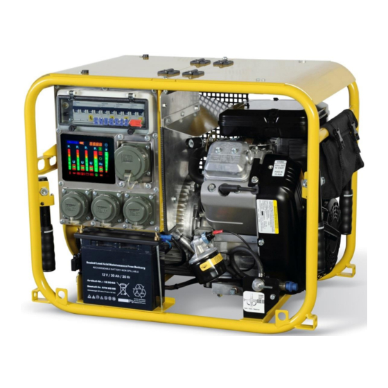
Endress ESE 604 DBG DIN Manuals
Manuals and User Guides for Endress ESE 604 DBG DIN. We have
1
Endress ESE 604 DBG DIN manual available for free PDF download: Operating Instructions Manual
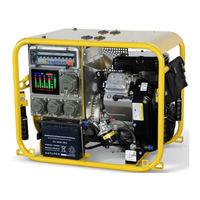
Endress ESE 604 DBG DIN Operating Instructions Manual (91 pages)
Brand:
Endress
| Category:
Portable Generator
| Size: 3 MB
Table of Contents
Operating Instructions
1
Endress
2
Table of Contents
3
Elektrogerätebau Gmbh
2
E132569
2
1 General Information
9
Further Documents
10
Used Signs and Symbols
11
General Signs / Symbols
11
Advanced Organizer
11
Note
11
Safety Symbols
12
General Hazard Warning
12
Potentially Explosive Materials
12
Dangerous Electrical Voltage
12
Poisonous Substances
12
Environmentally Damaging Substances
12
Hot Surfaces
12
Notes
13
2 General Safety Regulations
14
Important Safety Warning
14
Intended Use
15
Foreseeable Incorrect Use or Inappropriate Handling
16
Residual Risks
17
Operating Personnel - Qualifications and Obligations
19
Personal Protective Equipment
19
Danger Zones and Work Areas
20
Table 2.1: Danger Zones and Work Areas on the Generator
20
Signs on the Generator
21
Figure 2-1: Signs on the Generator
21
Table 2.2: Signs on the Generator
22
General Safety Instructions
23
Notes
27
3 Description of the ESE 604 / 954 DBG DIN Generator
28
Components of the ESE 604 / 954 DBG DIN Generator
28
Fig. 3-1: Views of the Generator
28
Components of the Operating and Generator Side
29
Fig. 3-2: Components of the Operating and Generator Side
29
Exhaust and Engine Side Components
30
Figure 3-3: Exhaust and Engine Side Components
30
Control Panel Components
31
Fig. 3-4: Control Panel Components
31
Accessory Components
32
Figure 3-5: Components of the Standard Accessories
32
Function and Mode of Operation
33
Fig. 3-6: Components of the Special Accessories
33
Notes
34
4 Operating the ESE 604 / 954 DBG DIN Generator
35
Transporting the Generator
35
Setting up the Generator
35
Set up the Generator as Follows
36
Refuelling the Generator
36
Refuel the Generator as Follows
37
Starting the Generator
37
Start the Engine as Follows
38
Figure 4-1: Started by Hand
39
Figure 4-2: Electrical Start
40
Switching the Generator off
41
The Device Is Switched off as Follows
41
Connecting up to Consumers
42
Switch the Consumer on as Follows
42
Fig. 4-3: Connecting up to Consumers
42
Switch the Consumer off as Follows
43
Disconnect a Consumer from the Control Panel as Follows
43
Check the Protective Conductor (Valid for Devices up to Year of Construction 12/2015)
44
Figure 4-4: Check the Protective Conductor
44
Table 4.1: Protective Conductor Test Lamp
45
Monitoring the Operating Status Using the Multifunction Display
46
Figure 4-5: Multi-Functional Display
46
Putting the Generator out of Service
49
Disposal
49
Notes
50
5 Special Fittings / Using Accessories
51
FI Protection Switch
51
Figure 5-1: FI Protection Switch
52
Table 5.1: FI Protection Switch Test
52
Insulation Monitoring Using E-MCS 4.0
53
Insulation Monitoring Without Switching off
53
Figure 5-2: Insulation Monitoring Using E-MCS 3.0
53
Table 5.2: Insulation Monitoring Without Switching off
53
Insulation Monitoring with Switch off
54
Table 5.3: Insulation Monitoring Whilst Running Without Switching off
54
Table 5.4: Insulation Monitoring Plus Switching off
55
Table 5.5: Insulation Monitoring Whilst Running Without Switching off
55
Speed Lowering in Idle
56
Switch on Idle Speed Reduction as Follows
56
Switch the Idle down off as Follows
56
Figure 5-3: Switching the Idle down on Pressure Switch
56
Remote Start Device
57
Connect up the Remote Start Device as Follows
57
Figure 5-4: Connecting up a Remote Start Device
57
Disconnect the Remote Start Device as Follows
58
Start the Engine Manually as Follows
58
Figure 5-5: Electrical Start in Combination with Remote Start
58
The Device Is Switched off as Follows
59
External Start Device
60
Connect up the External Start Device as Follows
60
Disconnect the External Start Device as Follows
60
Figure 5-6: Connecting up an External Start Device
60
Battery Charge Retention
61
Disconnect the Battery Charge Conservation Device as Follows
61
Figure 5-7: Connecting up the Battery Charge Retention Device
61
Disconnect the Battery Charge Conservation Device as Follows
62
Fig. 5-8: Connecting up the Battery Charge Retention Device
62
Disconnect the Battery Charge Conservation Device as Follows
63
Fig. 5-9: Connecting up the Battery Charge Retention Device
63
3-Way Fuel Valve / Refuelling Device
64
Figure 5-10: 3-Way Fuel Valve
64
Table 5.6: Switchingpositions of the 3-Way Fuel Tap
64
Connect up Fuelling Device as Follows
65
Figure 5-11: Connect up Fuelling Device
65
Connect the Canister to the Fuelling Device as Follows
66
Exhaust Hose
67
Connect up the Exhaust Hose as Follows
67
Fig. 5-12 Connecting the Exhaust Hose
67
Disconnect the Exhaust Hose from the Generator by
68
6 Servicing and Maintaining the ESE 604 / 854 DBG DIN Generator
69
Maintenance Plan
69
Table 6.1: Generator Maintenance Plan
69
Maintenance Work
70
Motor Oil
70
Figure 6-1: Oil Dipstick
70
Check the Oil Level as Follows
71
Pour in Oil as Follows
71
Figure 6-2: Changing the Oil
71
Replacing the Starter Battery
73
Figure 6-3: Replacing the Battery
73
Replacing Fuses
74
Fig. 6-4: Replacing a Fuse
74
Table 6.2: Location of the Fuses
74
Checking the Electrical Safety
75
7 Troubleshooting
76
Table 7.1: Problems Arising During Generator Operation
78
Notes
79
8 Technical Specifications
80
Fig. 8-1: Generator Dimensions
80
Table 8.1: Generator Technical Data
81
Table 8.2: Ambient Conditions for the Generator
82
Table 8.3: Generator Power Reduction Dependent on Ambient Conditions
82
Table 8.4: Maximum Line Length of the Distribution Network as a Function of the Cable Cross-Section
82
Notes
83
9 Replacement Parts
84
Frame with Covers, Tank and Engine
84
Figure 9-1: Operating and Alternator Side Replacement Parts
84
Fig. 9-2: Engine and Exhaust Side Replacement Parts
85
Table 9.1: Replacement Parts for Covers
86
Generator and Electronics
87
Fig. 9-3: Replacement Parts Generator and Electronics
87
Table 9.2: Replacement Parts for an Engine with an Exhaust and Fuel System
88
Fuses
89
Figure 9-4: Replacement Parts for Fuses
89
Table 9.3: Replacement Parts for Fuses
89
Accessories and Markings
90
Fig. 9-5: Replacement Parts Accessories
90
Fig. 9-6: Replacement Parts Forspecial Accessories
91
Table 9.4: Replacement Parts for Accessories / Special Accessories
91
Advertisement
Advertisement
Related Products
Endress ESE 607 DBG ES DIN
Endress ESE 67 IW
Endress ESE 67 RS
Endress ESE 606 HS-GT ES
Endress ESE 606 HS-GT
Endress ESE 606 DHS-GT
Endress ESE 1306 HS-GT ES
Endress ESE 957 DBG ES DIN
Endress ESE 954 DBG DIN
Endress ESE 1307 DBG DIN
Endress Categories
Portable Generator
Inverter
Garage Door Opener
Water Pump
Telephone Accessories
More Endress Manuals
Login
Sign In
OR
Sign in with Facebook
Sign in with Google
Upload manual
Upload from disk
Upload from URL