Sign In
Upload
Manuals
Brands
Emerson Manuals
Controller
ROC809
Emerson ROC809 Manuals
Manuals and User Guides for Emerson ROC809. We have
2
Emerson ROC809 manuals available for free PDF download: Instruction Manual
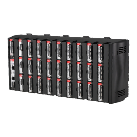
Emerson ROC809 Instruction Manual (184 pages)
ROC800 Series Remote Operations Controller
Brand:
Emerson
| Category:
Controller
| Size: 7.82 MB
Table of Contents
Table of Contents
3
Chapter 1 - General Information
7
Roc800L
7
Roc827
7
Scope of Manual
8
Series 1 Versus Series 2 Architecture
9
Dial-Up Modem
10
Hardware
11
Discrete Inputs
13
Discrete Outputs
13
Communication Modules
14
Central Processor Unit (CPU)
15
Real-Time Clock (RTC)
15
Diagnostic Monitoring
15
Options
16
FCC Information
17
Firmware
17
Historical Database and Event & Alarm Log
21
Meter Runs and Stations
22
ROC800 Flow Calculations
22
ROC800L Flow Calculations
23
Automatic Self Tests
23
Low Power Modes
24
Proportional, Integral, and Derivative (PID)
25
Function Sequence Table (FST)
25
ROCLINK 800 Configuration Software
26
ROCLINK 800 Dynamic Graphical Interface
27
ROC800L Software
28
DS800 Development Suite Software
29
Expansion Backplane
30
Foundation™ Fieldbus Interface
30
OUNDATION Fieldbus Interface
30
Security Gateway
30
Additional Technical Information
31
Chapter 2 - Installation and Use
33
Installation Requirements
33
Environmental Requirements
34
Site Requirements
34
Compliance with Hazardous Area Standards
35
Power Installation Requirements
35
Grounding Installation Requirements
36
I/O Wiring Requirements
37
Required Tools
37
Housing
37
Removing and Replacing End Caps
37
Removing and Installing Wire Channel Covers
38
Removing and Installing Module Covers
38
Mounting the ROC800 on a DIN Rail
39
Installing the DIN Rail
40
Securing the ROC800 to the DIN Rail
41
Removing the ROC800 from the DIN Rail
41
ROC800-Series Expansion Backplane (EXP)
41
Attaching an Expansion Backplane
42
ROC827 and Expansion Backplane
42
Removing an Expansion Backplane
43
Central Processing Unit (CPU)
45
Removing the CPU Module
49
Installing the CPU Module
49
License Keys
50
Installing a License Key
51
Removing a License Key
51
Startup and Operation
52
Startup
52
Operation
53
Chapter 3 - Power Connections
55
Power Input Module Descriptions
55
12-Volt DC Power Input Module (PM-12)
55
24-Volt DC Power Input Module (PM-24)
57
30-Volt DC Power Input Module (PM-30)
58
Auxiliary Output (AUX+ and AUX-)
62
Switched Auxiliary Output (AUXSW+ and AUXSW-)
64
Determining Power Consumption
65
DI Modules
68
DO Modules
68
DOR Modules
68
Tuning the Configuration
69
Description
70
Duty Cycle
70
Analog Input
70
Removing a Power Input Module
79
Installing a Power Input Module
81
Connecting the ROC800 to Wiring
81
Wiring the DC Power Input Module
82
Wiring the External Batteries
83
Replacing the Internal Battery
84
Additional Technical Information
86
Chapter 4 - Input/Output Modules
87
I/O Module Overview
87
Discrete Input
89
Installation
90
Removing and Installing Wire Channel Covers
90
Removing and Installing Module Slot Covers
91
Installing an I/O Module
91
Removing an I/O Module
93
Wiring I/O Modules
93
Analog Input (AI) Modules
93
Analog Output (AO) Modules
95
Discrete Input (DI) Modules
96
Analog Output Module
96
Discrete Input Module
97
Pulse Input (PI) Modules
98
Discrete Output (DO) Modules
99
Discrete Output Module
100
Discrete Output Relay (DOR) Modules
101
Resistance Temperature Detector (RTD) Input Modules
102
Field Wiring
102
Advanced Pulse Module (APM)
104
DIP Switches
106
Multi-Variable Sensor Input/Output (MVS I/O)
107
Pulse Input
107
Alternating Current Input/Output (AC I/O) Module
112
Thermocouple (TC) Input Module
114
Field Wiring
114
Highway Addressable Remote Transducer (HART ) Module
118
IEC 62591 Module
120
APP 485 Module
122
Additional Technical Information
123
Chapter 5 - Communications
125
Communication Ports and Modules Overview
125
Local Port
125
Installing Communication Modules
127
Communication Module
128
Removing a Communication Module
129
Wiring Communication Modules
129
Local Operator Interface (LOI)
129
Direct Connect
130
Using the LOI
131
Ethernet Communication
131
Tcp/Ip
131
RS-232) Serial Communication
133
EIA-422/485 (RS-422/485) Serial Communications Module
134
Built-In Comm2
134
Module Comm3 to Comm5
134
EIA-422/485 (RS-422/485) Communication
134
EIA-422/485 (RS-422/485) Jumpers & Termination Resistors
135
Dial-Up Modem Communication Module
137
Multi-Variable Sensor (MVS) Interface Module
138
Network Radio Module (NRM)
138
Additional Technical Information
140
Chapter 6 - Troubleshooting
141
Guidelines
141
Checklists
142
Serial Communications
142
I/O Point
143
Software
143
Powering up
144
MVS or MVS I/O Module
144
IEC 62591 Module
145
Procedures
145
Preserving Configuration and Log Data
145
Restarting the ROC800
145
Troubleshooting Analog Input Modules
146
Troubleshooting Analog Output Modules
148
Troubleshooting Discrete Input Modules
149
Troubleshooting Discrete Output Modules
149
Troubleshooting Discrete Output Relay Modules
150
Troubleshooting Pulse Input Modules
150
Troubleshooting RTD Input Modules
151
Troubleshooting Thermocouple Input (T/C) Modules
152
Troubleshooting Advanced Pulse Modules
154
Network Radio Modules
154
Chapter 7 - Calibration
157
Calibration Overview
157
Calibration Frequency
157
Preparing for Calibration
158
Appendix A - Glossary
159
Analog Output
162
Appendix B - Wiring Diagrams
167
Daniel Senior Sonic Meter to PI Module
167
Daniel Senior Sonic Meter
167
Daniel 1818A and 1838 Turbine Pre-Amp to PI Module
168
Micro Motion RFT9739 & 2400S Transmitters to PI Module
169
Micro Motion RFT9739 & 2400S Transmitters to APM Module
170
3- and 4-Wire RTD to RTD Module
171
Daniel Senior Sonic Meter to APM Module
172
Daniel 1818A and 1838 Dual Turbine Pre-Amp to APM Module
173
Daniel 1818A and 1838 Turbine Pre-Amp to APM Module
174
Two-Stage Valve with Two Limit Switches to ACIO Module
175
Advertisement
Emerson ROC809 Instruction Manual (174 pages)
ROC800 Series Remote Operations Controller
Brand:
Emerson
| Category:
Controller
| Size: 6.25 MB
Table of Contents
Table of Contents
3
Chapter 1 - General Information
7
Roc800L
7
Exp
7
Roc827
7
Scope of Manual
8
Series 1 Versus Series 2 Architecture
9
Dial-Up Modem
10
Hardware
11
Discrete Inputs
13
Discrete Outputs
13
Central Processor Unit (CPU)
14
Diagnostic Monitoring
15
Real-Time Clock (RTC)
15
Options
16
FCC Information
16
Firmware
17
Historical Database and Event & Alarm Log
21
Meter Runs and Stations
21
ROC800 Flow Calculations
22
ROC800L Flow Calculations
23
Automatic Self Tests
23
Low Power Modes
24
Proportional, Integral, and Derivative (PID)
24
Function Sequence Table (FST)
25
ROCLINK 800 Configuration Software
25
ROC800L Software
27
DS800 Development Suite Software
28
Expansion Backplane
29
FOUNDATION ™ Fieldbus Interface
29
Additional Technical Information
29
Chapter 2 - Installation and Use
31
Installation Requirements
31
Environmental Requirements
32
Site Requirements
32
Compliance with Hazardous Area Standards
33
Power Installation Requirements
34
Grounding Installation Requirements
34
I/O Wiring Requirements
35
Required Tools
35
Housing
35
Removing and Replacing End Caps
36
Removing and Installing Wire Channel Covers
36
Removing and Installing Module Covers
37
Mounting the ROC800 on a DIN Rail
37
Installing the DIN Rail
39
Securing the ROC800 to the DIN Rail
39
Removing the ROC800 from the DIN Rail
40
ROC800-Series Expansion Backplane (EXP)
40
ROC827 and Expansion Backplane
40
Attaching an Expansion Backplane
41
Removing an Expansion Backplane
42
Central Processing Unit (CPU)
43
Cpu
44
CPU Connectors
44
License Key
44
Removing the CPU Module
46
Installing the CPU Module
47
License Keys
47
Installing a License Key
48
Removing a License Key
49
Startup and Operation
49
Startup
50
Operation
50
Chapter 3 - Power Connections
51
Power Input Module Descriptions
51
12-Volt DC Power Input Module (PM-12)
51
Roc800
51
24-Volt DC Power Input Module (PM-24)
53
Auxiliary Output (AUX+ and AUX-)
54
Auxiliary Power Wiring for PM-12 Module
55
Auxiliary Power Wiring for PM-24 Module
55
Switched Auxiliary Output (AUXSW+ and AUXSW-)
56
Determining Power Consumption
57
DI Modules
60
DO Modules
60
DOR Modules
60
Tuning the Configuration
61
Analog Input
62
Description
62
Duty Cycle
62
Removing a Power Input Module
70
Installing a Power Input Module
71
Connecting the ROC800 to Wiring
72
Wiring the DC Power Input Module
72
Volts DC Power Supply and BAT+ / BAT
73
Wiring the External Batteries
74
Replacing the Internal Battery
76
Additional Technical Information
77
Chapter 4 - Input/Output Modules
79
I/O Module Overview
79
Optional I/O Module Locations
80
Installation
81
Removing and Installing Wire Channel Covers
82
Removing and Installing Module Slot Covers
82
Installing an I/O Module
83
Removing an I/O Module
84
Wiring I/O Modules
85
Analog Input (AI) Modules
85
Analog Input Module Field Wiring
86
Analog Output (AO) Modules
87
Discrete Input (DI) Modules
88
Analog Output Module
88
Discrete Input Module
89
Pulse Input (PI) Modules
90
Field Wiring
91
Discrete Output (DO) Modules
92
Discrete Output Relay (DOR) Modules
93
Discrete Output Relay
93
Discrete Output Module
93
Resistance Temperature Detector (RTD) Input Modules
95
Field Wiring
95
Advanced Pulse Module (APM)
96
DIP Switches
99
Thermocouple (TC) Input Module
100
Highway Addressable Remote Transducer (HART)
103
HART Module
105
Multi-Variable Sensor Input/Output (MVS I/O)
106
Alternating Current Input/Output (AC I/O) Module
110
Additional Technical Information
113
Chapter 5 - Communications
115
Communication Ports and Modules Overview
115
Mvs
115
Local Port
115
Installing Communication Modules
117
Removing a Communication Module
118
Wiring Communication Modules
119
Local Operator Interface (LOI)
119
Direct Connect
119
Using the LOI
121
Ethernet Communication
121
Tcp/Ip: 10.0.02
121
RS-232) Serial Communication
123
EIA-422/485 (RS-422/485) Serial Communications Module
124
Built-In Comm2
124
EIA-422/485 (RS-422/485) Communication
124
Module Comm3 to Comm5
124
EIA-422/485 (RS-422/485) Jumpers & Termination Resistors
125
Dial-Up Modem Communication Module
127
Multi-Variable Sensor (MVS) Interface Module
128
Additional Technical Information
129
Communication Module
129
Chapter 6 - Troubleshooting
131
Guidelines
131
Checklists
132
Serial Communications
132
I/O Point
133
Software
133
Analog Output
133
Powering up
134
MVS or MVS I/O Module
134
Procedures
134
Preserving Configuration and Log Data
135
Restarting the ROC800
135
Troubleshooting Analog Input Modules
136
Troubleshooting Analog Output Modules
137
Troubleshooting Discrete Input Modules
139
Troubleshooting Discrete Output Modules
139
Troubleshooting Discrete Output Relay Modules
140
Troubleshooting Pulse Input Modules
140
Troubleshooting RTD Input Modules
141
Troubleshooting Thermocouple Input (T/C) Modules
142
Troubleshooting Advanced Pulse Modules
143
Chapter 7 - Calibration
145
Calibration Overview
145
Calibration Frequency
145
Preparing for Calibration
146
Appendix A - Glossary
147
Discrete Input
149
Discrete Output
149
Pulse Input
154
Appendix B - Wiring Diagrams
159
Daniel Senior Sonic Meter to PI Module
159
Daniel Senior Sonic Meter
159
Daniel 1818A and 1838 Turbine Pre-Amp to PI Module
160
Micro Motion RFT9739 & 2400S Transmitters to PI Module
161
Micro Motion RFT9739 & 2400S Transmitters to APM Module
162
3- and 4-Wire RTD to RTD Module
163
Daniel Senior Sonic Meter to APM Module
164
Daniel 1818A and 1838 Dual Turbine Pre-Amp to APM Module
165
Daniel 1818A and 1838 Turbine Pre-Amp to APM Module
166
Two-Stage Valve with Two Limit Switches to ACIO Module
167
Index
169
Advertisement
Related Products
Emerson ROC827
Emerson TARTARINI RP/022/66
Emerson Bettis RPE 0025
Emerson Bettis RPE 0200
Emerson Bettis RPE 4000
Emerson Leroy-Somer R220
Emerson PACSystems RX3i IC695CPL410
Emerson PACSystems RX3i IC695CPE400
Emerson Leroy Somer R450
Emerson Bettis RP4AF
Emerson Categories
Controller
Control Unit
Transmitter
Measuring Instruments
Fan
More Emerson Manuals
Login
Sign In
OR
Sign in with Facebook
Sign in with Google
Upload manual
Upload from disk
Upload from URL