Sign In
Upload
Manuals
Brands
Emerson Manuals
I/O Systems
PACSystems RSTi-EP-711F
Emerson PACSystems RSTi-EP-711F Manuals
Manuals and User Guides for Emerson PACSystems RSTi-EP-711F. We have
1
Emerson PACSystems RSTi-EP-711F manual available for free PDF download: User Manual
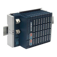
Emerson PACSystems RSTi-EP-711F User Manual (541 pages)
Analog Input Module
Brand:
Emerson
| Category:
I/O Systems
| Size: 31 MB
Table of Contents
Table of Contents
3
Introduction
16
Revisions in this Manual
17
Pacsystems Documentation
18
Pacsystems Manuals
18
Rx3I Manuals
18
System Overview
19
Dimensions of the Rsti-EP Components
20
Double-Click Installation
20
General Description of the Fieldbus Network Adapters
21
General Technical Data for the Fieldbus Network Adapter
22
General Description of I/O Modules
23
I/O Module (Example EP-1214)
23
Color Coding
24
Standard Connector
25
Features and Specifications
25
HD Connector EP-8360
26
Cable Protection
28
General Technical Data for I/O Modules
29
Mechanical Fixing Elements
31
Type Plate
31
Markers
32
Swivel Marker
32
Safety
33
General Safety Notice
33
Electrostatic Discharge
33
Open Equipment
34
Fusing
34
Earthing (Functional Earth FE)
34
Shielding
35
Overcurrent
35
Intended Use
35
Use in a Potentially Explosive Atmosphere
35
ATEX Zone 2
36
ATEX & Iecex Marking
37
Legal Notice
37
Use of Rsti-EP Stations 2,000M above Sea Level
37
Example
37
Configuration
38
Order and Arrangement of Modules
38
Arrangement of Safe Power-Feed Modules
39
Power Supply Concept
39
Clearances
40
Calculation of Space Requirements
42
Use in a Potentially Explosive Atmosphere
42
ATEX & Iecex Marking
43
Spring-Style System Cabling
43
Current Demand and Power Supply
43
Power Supply Derating
44
Example Calculation for the Power Supply
45
Calculation of the Current Demand for the Input Current
45
Calculation of the Current Demand for the Output Current
46
Example Calculation for the Current Demand (All Current Values in Amps)
47
Calculation of Power Loss
48
Calculation of Power Loss for Use in a Potentially Explosive Atmosphere
48
Feedback Energy in DO Modules
49
Calculation of Feedback Energy
49
Parameter Overview
50
Modifiable Parameters for Network Adaptors
50
Data Width of I/O Module, Dependent on the Network Adapter Used
65
Epxpbs001
65
Epxpns001/Epxpns101
67
Epxetc001
69
Epxeip001
70
Detailed Descriptions of the Fieldbus Network Adapters
73
Profibus DP Network Adapter EPXPBS001
73
Leds
74
LED Status Indicators
74
Addressing
75
Addressing Examples
76
Connection Diagrams
77
Specifications: EPXPBS001
78
Modifiable Parameters EPXPBS001
79
Supported Modules and Power Supplies
80
PROFINET IRT/RT Network Adapter EPXPNS001/EPXPNS101
82
Leds
83
Led Indicators
84
Connection Diagrams
85
Specification: EPXPNS001/EPXPNS101
86
Modifiable Parameters: EPXPNS001/EPXPNS101
88
Network Adaptor Input Status Data
89
Hot Standby CPU Redundancy I/O Parameters (EPXPNS101)
90
Rsti-EP PROFINET Channel Diagnostic Alarm Reporting
91
Supported Modules and Power Supplies
101
Ethercat ® Network Adapter EPXETC001
102
Leds
103
Connection Diagrams
105
Specifications: EPXETC001
106
Modifiable Parameters for EPXETC001
107
Rsti-EP Status Messages
107
Module Status Messages
108
Module Diagnosis
108
Supported Modules and Power Supplies
109
Modbus ® TCP Network Adapter EPXMBE001/EPXMBE101
111
Leds
112
Connection Diagrams
113
Specifications: EPXMBE001/EPXMBE101
114
Configuration of the IP Address
115
Modifiable Parameters for EPXMBE001/EPXMBE101
115
Register Structure
116
Implemented Modbus Functions
119
Supported Modules and Power Supplies
119
Packed Process Data
121
Packed Input Process Data
121
Packed Output Process Data
121
0X1000 - 0X1006 Network Adapter Identifier
123
0X1000 - 0X1006 Network Adapter Status
123
0X1010 Process Image Length in Bits for the Output Modules
123
0X1010 Process Image Length in Bits for the Input Modules
123
0X1017 Register - Mapping Revision
123
0X1018 - 0X101B Collective Diagnostics Message for I/O Modules
124
0X101C - 0X101F Collective Process Message for I/O Modules
124
0X1028 - 0X102F Module Status
124
0X1030 MODBUS DATA EXCHANGE Watchdog, Current Time
124
0X1120 MODBUS DATA EXCHANGE Watchdog, Predefined Time
125
0X1121 MODBUS DATA EXCHANGE Watchdog Reset Register
125
0X1122 Lock Force Mode on Web Server
125
0X1031 MODBUS CONNECTION Mode Register
125
0X1131 MODBUS CONNECTION Timeout in Sec
125
0X1132 Check Reference List Prior to Data Exchange
126
0X1133 Process Alarm
126
0X1134 Diagnostic Alarm
126
0X1135 Field Bus or Reference List Error Behavior
126
0X1136 Module Removal Behavior
126
0X1137 Data Format
126
0X113C - 0X113F Save Module Parameters
127
0X27Fe Number of Entries in the Current Module List
128
0X27Ff Number of Entries in the Reference Module List
128
0X2800 - 0X287F Reference Module List
128
0X2A00 - 0X2A7F Current Module List
128
0X2B00 - 0X2B7F Module Offsets of Process Data
128
0X8000 - 0X87Ff Process Data Inputs
128
0X9000 - 0X97Ff Process Data Outputs
129
0Xa000 - 0Xa7Ff Diagnostics
129
0Xb000 - 0Xb7Ff Process Alarms
129
0Xc000 -0Xffff Parameters
129
Ethernet/Ip™ Network Adapter EPXEIP001
130
Leds
131
Connection Diagrams
133
Specifications: EPXEIP001
134
Modifiable Parameters for EPXEIP001
135
Data Types EPXEIP001
138
Process Data
140
Status Word EPXEIP001(Packed Process Data Input)
142
Object Descriptions EPXEIP001: CIP Common Classes
143
Object Descriptions EPXEIP001: Vendor Specific Classes
149
Supported Modules and Power Supplies
152
Detailed Description of I/O Modules
154
Digital Input Module EP-1214
154
LED Indicators EP-1214
155
Specifications EP-1214
156
Modifiable Parameters for EP-1214
156
Diagnostic Data EP-1214
157
Process Data Inputs EP-1214
158
Digital Input Module EP-1218
158
LED Indicators EP-1218
159
Specifications EP-1218
160
Modifiable Parameters for EP-1218
160
Diagnostic Data EP-1218
160
Process Data Inputs EP-1218
162
Digital Input Module EP-1318
162
LED Indicators EP-1318
163
Specifications EP-1318
164
Modifiable Parameters for EP-1318
164
Diagnostic Data EP-1318
165
Process Data Inputs EP-1318
166
Digital Input Module EP-1804
166
LED Indicators EP-1804
167
Specifications EP-1804
168
Diagnostic Data EP-1804
168
Process Data Inputs EP-1804
170
Digital Input Module EP-125F
170
LED Indicators EP-125F
171
Specifications EP-125F
172
Diagnostic Data EP-125F
172
Process Data Inputs EP-125F
173
Digital Input Module EP-12F4
173
LED Indicators EP-12F4
175
Specifications EP-12F4
176
Modifiable Parameters for EP-12F4
177
Diagnostic Data EP-12F4
177
Process† Data Inputs EP-12F4
178
Time Stamp Function
178
Structure of an ETS Entry
179
Digital Input Module EP-153F
182
LED Indicators EP-153F
183
Specifications EP-153F
184
Diagnostic Data EP-153F
184
Process Data Inputs EP-153F
185
Digital Output Module EP-2214
186
LED Indicators EP-2214
187
Specifications EP-2214
188
Modifiable Parameters for EP-2214
189
Diagnostic Data EP-2214
189
Process Data Outputs EP-2214
190
Digital Output Module EP-2614
190
LED Indicators EP-2614
191
Specifications EP-2614
192
Modifiable Parameters for EP-2614
193
Diagnostic Data EP-2614
193
Process Data Outputs EP-2614
194
Digital Output Module EP-2634
194
LED Indicators EP-2634
195
Specifications EP-2634
196
Modifiable Parameters for EP-2634
197
Diagnostic Data EP-2634
197
Process Data Outputs EP-2634
197
Digital Output Module EP-2218
198
LED Indicators EP-2218
198
Specifications EP-2218
200
Modifiable Parameters for EP-2218
200
Diagnostic Data EP-2218
200
Process Data Outputs EP-2218
202
Digital Output Module EP-225F
202
LED Indicators EP-225F
203
Specifications: EP-225F
204
Diagnostic Data EP-225F
205
Process† Data Outputs EP-225F
206
Digital Output Module EP-2814
207
LED Indicators EP-2814
208
Specifications EP-2814
209
Modifiable Parameters for EP-2814
209
Diagnostic Data EP-2814
209
Process Data Outputs EP-2814
210
Digital Output Module EP-2714
210
LED Indicators EP-2714
212
Specifications EP-2714
213
Modifiable Parameters for EP-2714
214
Diagnostic Data EP-2714
215
Process Data Outputs EP-2714
216
Digital Output Module EP-291F
216
LED Indicators EP-291F
217
Specifications: EP-291F
218
Diagnostic Data EP-291F
219
Data Outputs EP-291F
220
Digital Output Module EP-5111
221
LED Indicators EP-5111
222
Specifications EP-5111
223
Modifiable Parameters for EP-5111
224
Diagnostic Data EP-5111
226
Process Data† Inputs EP-5111
227
Process Data† Outputs EP-5111
227
Process Alarm Data EP-5111
229
Setting up the Counter
229
Counter Functions
230
Counting Mode
230
Counting Direction
230
Endless Counting
232
Additional Counter Features
237
Latch Function
237
Comparison Function
237
Pulse Duration
238
Digital Counter Module EP-5112
243
LED Indicators EP-5112
244
Specifications EP-5112
245
Modifiable Parameters for EP-5112
246
Diagnostic Data EP-5112
247
Process Data† Inputs EP-5112
248
Process Data† Outputs EP-5112
249
Process Alarms for EP 5112
250
Setting up the Counter
250
Counter Functions
251
Additional Counter Features
257
Digital Frequency Counter Module EP-5212
263
LED Indicators EP-5212
264
Specifications EP-5212
265
Modifiable Parameters for EP-5212
266
Diagnostic Data EP-5212
267
Process Data† Inputs EP-5212
268
Process Data† Outputs EP-5212
269
Function Frequency Counting
269
Start Measurement
269
Calculation of Results
270
Stop Measurement
270
Serial Communication Module EP-5261
272
LED Indicators EP-5261
275
Specifications EP-5261
276
Modifiable Parameters for EP-5261
277
Diagnostic Data EP-5261
277
Data Transfer
278
SSI Encoder Interface Module EP-5311
283
LED Indicators EP-5311
284
Specifications EP-5311
285
Modifiable Parameters for EP-5311
285
Diagnostic Data EP-5311
286
Process Data Inputs EP-5311
288
Digital Pulse Width Modulation Output Module EP-5422
288
LED Indicators EP-5422
289
Specifications EP-5422
290
Modifiable Parameters for EP-5422
291
Diagnostic Data EP-5422
291
Process† Data Inputs EP-5422
291
Process Data† Outputs EP-5422
292
Digital Pulse Width Modulation Output Module EP-5442
292
LED Indicators EP-5442
294
Specifications EP-5442
295
Modifiable Parameters for EP-5442
296
Diagnostic Data EP-5442
296
Process† Data Inputs EP-5442
297
Process Data† Outputs EP-5442
297
IO-Link Communication Module EP-5324
298
IO-Link Overview
299
LED Indicators EP-5324
303
Specifications EP-5324
304
Modifiable Parameters for EP-5324
304
Diagnostic Data EP-5324
308
Process Data Inputs EP-5324
310
Process Data Outputs EP-5324
311
Network Adapters-Dependent Process Data Widths
312
IO-Link Communication Module EP-5324 Event Codes
313
Analog Input Module EP-3164
314
LED Indicators EP-3164
315
Specifications EP-3164
316
Modifiable Parameters for EP-3164
317
Diagnostic Data EP-3164
317
Process Data† Inputs EP-3164
318
Measurement Range EP-3164
318
Analog Input Module EP-3264
320
LED Indicators EP-3264
321
Specifications EP-3264
322
Modifiable Parameters for EP-3164
323
Diagnostic Data EP-3264
323
Diagnostic Data EP-3264
324
Process Data† Inputs EP-3264
325
Measurement Range EP-3264
325
Analog Input Module EP-3664
327
LED Indicators EP-3664
328
Specifications: EP-3664
329
Modifiable Parameters EP-3664
330
Diagnostic Data EP-3664
330
Process Data† Inputs EP-3664
332
Measurement Range EP-3664
332
Analog Input Module EP-3124
334
LED Indicators EP-3124
335
Specifications EP-3124
336
Modifiable Parameters for EP-3124
337
Diagnostic Data EP-3124
337
Process Data† Inputs EP-3124
338
Measurement Range EP-3124
338
Measurement Range EP-3124
339
Analog Input Module EP-3368
340
LED Indicators EP-3368
341
Specifications EP-3368
342
Modifiable Parameters for EP-3368
343
Diagnostic Data EP-3368
343
Process Data† Inputs EP-3368
344
Measurement Range EP-3368
345
Analog Input Module EP-3468
345
LED Indicators EP-3468
346
Specifications EP-3468
347
Modifiable Parameters for EP-3468
348
Process Data
348
Inputs EP-3468
348
Diagnostic Data EP-3468
349
Measurement Range EP-3468
350
Analog Output Module EP-4164
351
LED Indicators EP-4164
352
Specifications EP-4164
353
Modifiable Parameters for EP-4164
354
Diagnostic Data EP-4164
354
Process Data Outputs EP-4164
355
Value Range
355
Analog Output Module EP-4264
357
LED Indicators EP-4264
358
Specifications EP-4264
359
Modifiable Parameters for EP-4264
360
Diagnostic Data EP-4264
360
Process Data Outputs EP-4264
362
Value Range† EP-4264
362
Analog Input Module EP-3704
364
LED Indicators EP-3704
365
Specifications EP-3704
366
Modifiable Parameters for EP-3704
367
Diagnostic Data EP-3704
368
Process Data
369
Inputs EP-3704
369
Resistance Measurement Range EP-3704
370
Temperature Measurement Ranges EP-3704
371
Process Alarm EP-3704
372
Analog Input Module EP-3804
373
LED Indicators EP-3804
374
Specifications EP-3804
375
Modifiable Parameters for EP-3804
376
Diagnostic Data EP-3804
377
Process Data Inputs EP-3804
379
Voltage Measurement Ranges EP-3804
379
Temperature Measurement Ranges EP-3804
379
Process Alarm EP-3804
381
Power Measurement Module EP-1813
382
LED Indicators EP-1813
387
Specifications EP-1813
388
Modifiable Parameters for EP-1813
389
Diagnostic Data EP-1813
392
Process Data Inputs EP-1813
393
Process Data Outputs EP-1813
394
Process Alarm
394
Conversion of the Adjustable Measuring Values EP-1813
395
Raw Parameter Data for Acyclic Services (Not Relevant with MODBUS Application)
397
Power-Feed Module for Input Current Path EP-7631
400
LED Indicators EP-7631
401
Specifications EP-7631
402
Power-Feed Module for Output Current Path EP-7641
402
LED Indicators EP-7641
403
Specifications EP-7641
404
Safe Feed-In Modules EP-1901, EP-1902, and EP-1922
405
Potential Distribution Module for Input Current Path EP-711F
406
Specifications EP-711F
407
Potential Distribution Module for Output Current Path EP-751F
408
Specifications EP-751F
409
Potential Distribution Module for Functional Earth EP-700F
410
Specifications EP-700F
411
0-V Potential Distribution Module for Input Current Path EP-710F
411
Specifications EP-710F
412
0-V Potential Distribution Module for Output Current Path EP-750F
413
Specifications EP-750F
414
Empty Slot Module EP-8310
414
Specifications EP-8310
415
Termination Kit EP-8301
415
Specifications EP-8301
415
Installation
416
Preparations for Assembly
416
Environmental Conditions
416
DIN Rail
416
Stripping Lengths
417
Unpacking and Delivery
417
Use in a Potentially Explosive Atmosphere
417
Installation Orientation
418
Clearances
419
Calculation of Space Requirements
420
Installation Sequence
421
Arrangement of SIL Modules
421
Preparation and the Required Tool
421
Assembling the Rsti-EP Station
422
Attaching the Marker
426
Attaching the Swivel Marker
426
Wiring
426
Wiring of Modules with Standard Connectors
427
Wiring of Modules with HD Connectors EP-8360
427
Insulation Test
428
Earthing and Shielding
430
Earthing of Shielded Cables
431
Shielded Cables Increase Interference Resistance
431
Proper Use of Shielded Cables
432
Effective Shielding
433
Potential Ratios
435
Basic Aspects
435
Potential-Free Design
435
Non-Isolated Design
436
Electromagnetic Compatibility (EMC)
436
Ensuring EMC
436
Earthing of Inactive Metal Parts
437
PE Connection
437
Unearthed Operation
437
DIN Rails
437
Cabinet Design According to EMC Guidelines
438
Shielding of Cables
439
Equipotential Bonding
440
Inductance Wiring
440
Commissioning
442
Requirements
442
Configuring EPXPNS001/EPXPNS101
443
Configuring EPXPNS001/EPXPNS101 Parameters
444
Data Format
446
Option Handling
447
Adding EPXPNS001/ EPXPNS101 Modules to a Remote Node
449
Configuring EPXPNS001/EPXPNS101 Module Parameters
450
Configuring EPXPBS001
450
Adding Slaves and Modules
450
Configuring Module Data Areas
454
Configuring DP-V1 Settings for a Slave
455
Configuring EPXETC001
458
Configuring EPXMBE001/EPXMBE101
461
Configuring EPXEIP001
461
Configuring EP-5324
463
Web Server
468
Requirements
469
Operating System
469
Browser
469
Device Drivers
469
Starting the Web Server
471
Activating the Ethernet Socket
471
Setting up Registration Data and Password Protection
473
Navigation and Operating Instructions
474
Setting the Language
474
Zooming the View In/Out
475
Quick View (Tooltip) of Detailed Values
475
Displaying and Editing the Network Adapter Status
476
Resetting the Web Server
477
Resetting the Network Adapter to Factory Settings
477
Accessing Network Adapter Parameters
478
Displaying Module Data and Editing Parameters
478
Displaying Node Information
480
Displaying Process Data
480
Displaying Diagnostic Data
480
Web Server in Force Mode
481
Open the Detail View of the Station in Force Mode
482
Filtering the Module View
483
Resetting Filters
483
Manually Switching Outputs (Forcing)
484
Modules with Registers
484
Ending/Deactivating Forced Operations
485
Updating Firmware
485
Recovery Mechanism for Rsti-EP Network Adapter
488
Web Server about Help
489
Exporting Log Data, Saving a Service File
489
Section 10: Replacing Components
490
Removing/Replacing the Plug-In Unit
490
Replacing the Electronic Unit
491
Replacing an I/O Module
496
Removing/Replacing Connectors
498
Removing/Replacing Cables
500
Section 11: Disassembly and Disposal
502
Disassembling the Rsti-EP Station
502
Disposing of the Rsti-EP Station
502
Section 12: LED Indicators and Troubleshooting
504
Fieldbus Network Adapters
505
I/O Modules
510
Section 13: IO-Link Device Configuration
517
Rsti-EP IO-Link Configurator
517
Installing Rsti-EP IO-Link Configurator
519
Operating the Rsti-EP IO-Link Configurator
519
Displaying the Starting Page
519
IO-Link Port Overview
521
IO-Link Device Detailed View
522
Displaying the Context Menu
523
Creating a New Project
523
Saving a Project
523
Opening a Project
523
Changing the Language
523
Opening the Ioddfinder in the Standard Browser
524
Editing IO-Link Device Configurations
524
Assigning the IO-Link Device to an IO-Link Port
524
Changing the Device Type
525
Removing the IO-Link Device Assignment
525
Editing the IO-Link Device Parameters
525
Determining the Process Data Length
526
Finding & Rectifying Parameter Errors
526
Editing IO-Link Device Configurations Online
527
Connecting to the Network Adapter
527
Activating an IO-Link Port
527
Deactivating an IO-Link Port
528
Identifying a Connected IO-Link Device
528
Downloading Iodds for a Connected IO-Link Device
529
Reading out IO-Link Device Parameters
529
Writing IO-Link Device Parameters
529
Displaying Process Data
530
Displaying Diagnosis
530
Section 14: Accessories and Replacement Parts
531
Accessories
531
Replacement Parts
531
Replacement Parts for Network Adapters
532
Replacement Parts for Modules
532
Appendix A: Decimal & Hexadecimal
534
Conversion Table
534
Appendix B: Marine Certification Table
535
Analog Output Modules
536
Appendix C: Serial Number Tracking Table
537
General Contact Information
540
Technical Support
540
Advertisement
Advertisement
Related Products
Emerson PACSystems RSTi-EP-7641
Emerson PACSystems RSTi-EP-7631
Emerson PACSystems RSTi-EP-751F
Emerson PACSystems RSTi-EP-1214
Emerson PACSystems RSTi-EP-125F
Emerson PACSystems RSTi-EP-12F4
Emerson PACSystems RSTi-EP-2214
Emerson PACSystems RSTi-EP-2714
Emerson PACSystems RSTi-EP-2814
Emerson PACSystems RSTi-EP-3804
Emerson Categories
Controller
Control Unit
Transmitter
Measuring Instruments
Fan
More Emerson Manuals
Login
Sign In
OR
Sign in with Facebook
Sign in with Google
Upload manual
Upload from disk
Upload from URL