Sign In
Upload
Manuals
Brands
eMachines Manuals
Laptop
D520 2890 - eMachines - Celeron 2 GHz
eMachines D520 2890 - eMachines - Celeron 2 GHz Manuals
Manuals and User Guides for eMachines D520 2890 - eMachines - Celeron 2 GHz. We have
1
eMachines D520 2890 - eMachines - Celeron 2 GHz manual available for free PDF download: Service Manual
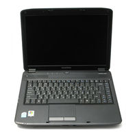
eMachines D520 2890 - eMachines - Celeron 2 GHz Service Manual (174 pages)
eMachines Laptop User Manual
Brand:
eMachines
| Category:
Laptop
| Size: 5.83 MB
Table of Contents
Table of Contents
7
Revision History
2
System Specifications
11
Features
11
Power Subsystem
12
Privacy Control
12
Special Keys and Controls
12
System Block Diagram
13
Your Acer Notebook Tour
14
Front View
14
Closed Front View
15
Rear View
15
Left View
16
Right View
17
Bottom View
18
Indicators
19
Touchpad Basics (with Fingerprint Reader)
20
Using the Keyboard
21
Lock Keys and Embedded Numeric Keypad
21
Windows Keys
22
Hot Keys
23
Special Key
24
Using the System Utilities
25
Acer Gridvista (Dual-Display Compatible)
25
Hardware Specifications and Configurations
26
System Utilities
31
BIOS Setup Utility
31
Navigating the BIOS Utility
31
Information
32
Main
33
Advanced
34
Security
36
Removing a Password
37
Setting a Password
37
Changing a Password
38
Power
39
Boot
41
Exit
42
BIOS Flash Utilities
43
DOS Flash Utility
44
Winflash Utility
46
Remove HDD/BIOS Password Utilities
47
Machine Disassembly and Replacement
51
Disassembly Requirements
51
General Information
52
Disassembly Process
52
Pre-Disassembly Instructions
52
External Module Disassembly Process
53
External Modules Disassembly Flowchart
53
Removing the Battery Pack
54
Removing the Lower Covers
55
Removing the DIMM Modules
57
Removing the WLAN Module
58
Removing the Hard Disk Drive Module
60
Removing the Optical Drive Module
62
Main Unit Disassembly Process
64
Main Unit Disassembly Flowchart
64
Removing the Switch Cover
65
Removing the Keyboard
67
Removing the Antenna
68
Removing the LCD Module
70
Removing the Upper Cover
72
Removing the Touchpad Bracket
75
Removing the Speaker Modules
77
Removing the Power Board
79
Removing the Modem Module
80
Removing the Main Board
81
Removing the CPU Fan
83
Removing the Thermal Module
84
Removing the CPU
85
LCD Module Disassembly Process
86
LCD Module Disassembly Flowchart
86
Removing the LCD Bezel
87
Removing the Inverter Board
88
Removing the Camera Module
89
Removing the LCD Panel
90
Removing the LCD Brackets and FPC Cable
91
Removing the Antennas
92
Removing the MIC Module
93
LCD Module Reassembly Procedure
94
Replacing the LCD Panel
94
Replacing the LCD Bezel
98
Main Module Reassembly Procedure
99
Replacing the CPU
99
Replacing the Thermal Module
99
Replacing the CPU Fan Module
100
Replacing the Mainboard
100
Replacing the Modem Module
101
Replacing the Power Board
102
Replacing the Speaker Module
103
Replacing the Touchpad Bracket
105
Replacing the Upper Case
105
Replacing the LCD Module
107
Replacing the Antenna Cable
109
Replacing the Keyboard
110
Replacing the Switch Cover
111
Replacing the ODD Module
112
Replacing the Hard Disk Drive Module
113
Replacing the DIMM Modules
114
Replacing the WLAN Module
114
Replacing the Lower Covers
115
Replacing the Battery
116
Troubleshooting
117
Common Problems
117
Power on Issue
118
No Display Issue
119
Random Loss of BIOS Settings
120
Built-In Keyboard Failure
121
LCD Failure
121
Internal Keyboard Failure
121
Internal Speaker Failure
122
Touchpad Failure
122
Sound Problems
123
Internal Microphone Failure
124
HDD Not Operating Correctly
125
ODD Failure
126
Modem Function Failure
129
Wireless Function Failure
129
Modem Failure
129
WLAN Failure
129
External Mouse Failure
130
Thermal Unit Failure
130
Other Failures
131
Other Functions Failure
131
Intermittent Failures
132
Intermittent Problems
132
Undermined Failures
132
Undetermined Problems
132
Post Codes
133
Memory
133
Sec
133
BDS & Specific Action
134
Each Driver Entry Point Used in 80_PORT
135
Each PEIM Entry Point Used in 80_PORT
135
Each Smmdriver Entry Point Used in 80_PORT
138
Jumper and Connector Locations
139
Top View
139
Bottom View
140
Clearing Password Check and BIOS Recovery
141
Clearing Password Check
141
Hardware Open Gap Description
141
BIOS Recovery by Crisis Disk
142
FRU (Field Replaceable Unit) List
143
Emachines D720/D520 Exploded Diagrams
144
Main Assembly
144
LCD Panel
145
Emachines D720/D520 FRU List
146
Screw List
150
Model Definition and Configuration
152
Emachines D720/D520 Series
152
Model Description
152
Test Compatible Components
163
Microsoft® Windows® Vista Environment Test
164
Online Support Information
171
Index
173
Advertisement
Advertisement
Related Products
eMachines D520 Series
eMachines D525 Series
eMachines D530 Series
eMachines D725 Series
eMachines D620 Series
eMachines D620 5150 - eMachines - Athlon 1.6 GHz
eMachines D732
eMachines D640 Series
eMachines D730 Series
eMachines D730Z Series
eMachines Categories
Laptop
Monitor
Desktop
Motherboard
Projector
More eMachines Manuals
Login
Sign In
OR
Sign in with Facebook
Sign in with Google
Upload manual
Upload from disk
Upload from URL