Sign In
Upload
Manuals
Brands
Em-Trak Manuals
Transceiver
A100
User Manuals: Em-Trak A100 AIS Transceiver
Manuals and User Guides for Em-Trak A100 AIS Transceiver. We have
3
Em-Trak A100 AIS Transceiver manuals available for free PDF download: Installation And User Manual, Product Manual, Fault Finding Manual
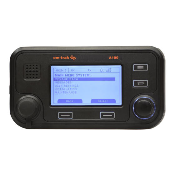
Em-Trak A100 Installation And User Manual (84 pages)
Fully integrated AIS Class A
Brand:
Em-Trak
| Category:
Transceiver
| Size: 6 MB
Table of Contents
Table of Contents
3
1 Notices
7
Safety Warnings
7
General Notices
7
2 Introduction
9
About AIS
9
Figure 1 the AIS Network
9
Static and Dynamic Vessel Data
10
AIS Operation Licensing
10
3 Operation
11
Display and Controls
11
Figure 2 Transceiver Front Panel
11
Turning the Transceiver on
12
Display Layout
12
Figure 3 Display Layout
12
Main Operating Screens
13
Figure 4 Selection of Main Operating Screen
13
Target List
14
Own Vessel and Voyage Data
14
Figure 5 Target List Screen and Vessel Details View
14
Figure 6 Own Vessel and Voyage Data Screen
14
Own Dynamic Data
15
Figure 7 Own Dynamic Data Screen
15
Received Messages
16
Figure 8 Received Messages Screen
16
Figure 9 Message Details View
16
Alarms Screen
17
Figure 10 Alarms Screen
17
Figure 11 Alarm Details View
17
Target Plot Screen
18
Working with AIS Text and Safety Related Messages (Srms)
18
Figure 12 Target Plot Screen
18
Figure 13 Target Plot Symbols
18
Figure 14 Safety Related Message Notification
19
Figure 15 Message Composition
19
Handling Alarms
20
Figure 16 Alarm Notification Screen
20
Entering Text
21
Figure 17 Text Entry
21
Long Range Messages
22
Figure 18 Long Range Interrogation Notification; Automatic Response Mode Enabled
22
Figure 19 Long Range Interrogation Notification; Manual Response Mode Enabled
22
Passwords and Security
23
Figure 20 Long Range Message List and Details Views
23
The Configuration Menu
24
Figure 21 Password Entry Screen
24
Figure 22 Main Menu Structure
25
Figure 23 Main Menu Screen
26
Figure 24 the Voyage Data Menu
26
Figure 25 the Messages Menu
27
Figure 26 the User Settings Menu
27
Figure 27 the Installation Menu
28
Figure 28 the Maintenance Menu
29
Figure 29 Diagnostics Menu
29
Tanker Mode
30
Units Display - Speed and Distance
30
Figure 30 Tanker Mode Entry Acknowledgement Screen
30
Figure 31 Tanker Mode Exit Screen When Speed Exceeds 3 Knots
30
Inland AIS
31
4 Installation
33
Figure 32 Typical AIS Transceiver Connection
33
What's in the Box
34
Figure 33 What's in the Box
34
Preparing for Installation
35
Installation Procedures
35
Figure 34 AIS Transceiver Dimensions
36
Figure 35 Mounting the AIS Transceiver
36
Figure 36 Panel Mounting the AIS Transceiver
37
Figure 37 Junction Box Dimensions
38
Figure 38 Mounting the Junction Box
38
Figure 39 GNSS Antenna Location
39
Figure 40 GNSS Antenna Connection
39
Figure 41 VHF Antenna Installation
40
Connecting the Equipment
41
Figure 42 VHF Antenna Connection
41
Figure 43 Connecting the Junction Box to the Transceiver
41
Figure 44 Junction Box Connections
43
Figure 45 Example Connection to External Display Equipment
45
Figure 46 Connecting Data Interface Cable Shields
45
Figure 47 Line Termination Options
46
Figure 48 Power Connection
46
Figure 49 Grounding the Transceiver
47
Figure 50 PC Data (RS232) Connection
48
Configuring the Transceiver
49
Figure 51 Vessel Dimensions Measurement
50
Changing the Password
52
Confirming Correct Operation
52
Regional Area Settings
52
Figure 52 Regional Areas List Screen
52
Figure 53 Regional Area Editing Screen
53
Figure 54 Regional Area Settings Confirmation Screen
53
Inland AIS
54
Figure 55 Blue Sign Switch Connection
56
5 Technical Specifications
57
Applicable Equipment Standards
57
Physical
57
Environmental
57
Electrical
57
Display and User Interface
58
Internal GNSS (Dual Mode GNSS Receiver Variants)
58
Internal GNSS (GPS Only Variants)
58
TDMA Transmitter
58
TDMA Receivers
59
DSC Receiver
59
RF Connections
59
Data Interfaces
60
Power and Data Connector Information
60
6 Technical Reference
61
Interface Sentences
61
Transmission Intervals
62
Sensor Data Input Port
62
Bi-Directional Data Ports
63
Output Drive Capability of Bi-Directional Ports
63
DGPS Port
63
RS232 Port
63
Input Data Sentence Formats
63
Output Data Sentence Formats
72
7 Drawings
76
AIS Transceiver Overall Dimensions
76
Junction Box Overall Dimensions
76
Dash Mount Bracket Fixing Holes (Drill Drawing) (Not to Scale)
77
GNSS Antenna Drawing (Not to Scale)
77
8 Annex a - ERI Ship Types
78
9 Installation Record
81
Data Interfaces
84
Advertisement
Em-Trak A100 Product Manual (81 pages)
Brand:
Em-Trak
| Category:
Transceiver
| Size: 4 MB
Table of Contents
Table of Contents
3
Installation Record
4
List of Figures
5
1 Notices
7
Safety Warnings
7
General Notices
7
Revision Information
8
2 Introduction
9
About AIS
9
Figure 1 the AIS Network
9
Static and Dynamic Vessel Data
10
AIS Operation Licensing
10
3 Operation
11
Display and Controls
11
Figure 2 Transceiver Front Panel
11
Turning the Transceiver on
12
Display Layout
12
Figure 3 Display Layout
12
Main Operating Screens
13
Figure 4 Selection of Main Operating Screen
13
Target List
14
Own Vessel and Voyage Data
14
Figure 5 Target List Screen and Vessel Details View
14
Figure 6 Own Vessel and Voyage Data Screen
14
Own Dynamic Data
15
Figure 7 Own Dynamic Data Screen
15
Received Messages
16
Figure 8 Received Messages Screen
16
Figure 9 Message Details View
16
Alarms Screen
17
Figure 10 Alarms Screen
17
Figure 11 Alarm Details View
17
Target Plot Screen
18
Working with AIS Text and Safety Related Messages (Srms)
18
Figure 12 Target Plot Screen
18
Figure 13 Target Plot Symbols
18
Figure 14 Safety Related Message Notification
19
Figure 15 Message Composition
19
Handling Alarms
20
Figure 16 Alarm Notification Screen
20
Entering Text
21
Long Range Messages
22
Figure 17 Text Entry
22
Figure 18 Long Range Interrogation Notification; Automatic Response Mode Enabled
23
Figure 19 Long Range Interrogation Notification; Manual Response Mode Enabled
23
Figure 20 Long Range Message List and Details Views
23
Passwords and Security
24
The Configuration Menu
24
Figure 21 Password Entry Screen
24
Figure 22 Main Menu Structure
25
Figure 23 Main Menu Screen
26
Figure 24 the Voyage Data Menu
26
Figure 25 the Messages Menu
27
Figure 26 the User Settings Menu
27
Figure 27 the Installation Menu
28
Figure 28 the Maintenance Menu
28
Tanker Mode
29
Figure 29 Diagnostics Menu
29
Figure 30 Tanker Mode Entry Acknowledgement Screen
29
Units Display - Speed and Distance
30
Inland AIS
30
Figure 31 Tanker Mode Exit Screen When Speed Exceeds 3 Knots
30
4 Installation
33
Figure 32 Typical AIS Transceiver Connection
33
What's in the Box
34
Figure 33 What's in the Box
34
Preparing for Installation
35
Installation Procedures
35
Figure 34 AIS Transceiver Dimensions
36
Figure 35 Mounting the AIS Transceiver
36
Figure 36 Panel Mounting the AIS Transceiver
37
Figure 37 Junction Box Dimensions
38
Figure 38 Mounting the Junction Box
38
Figure 39 GPS Antenna Location
39
Figure 40 GPS Antenna Connection
39
Figure 41 VHF Antenna Installation
40
Connecting the Equipment
41
Figure 42 VHF Antenna Connection
41
Figure 43 Connecting the Junction Box to the Transceiver
41
Figure 44 Junction Box Connections
43
Figure 45 Example Connection to External Display Equipment
45
Figure 46 Line Termination Options
45
Figure 47 Power Connection
46
Figure 48 PC Data (RS232) Connection
47
Configuring the A100 Transceiver
48
Figure 49 Vessel Dimensions Measurement
49
Changing the Password
51
Confirming Correct Operation
51
Regional Area Settings
51
Figure 50 Regional Areas List Screen
51
Figure 51 Regional Area Editing Screen
52
Figure 52 Regional Area Settings Confirmation Screen
52
Inland AIS
53
Figure 53 Blue Sign Switch Connection
55
5 Technical Specifications
57
Applicable Equipment Standards
57
Physical
57
Environmental
57
Electrical
57
Display and User Interface
58
Internal GPS
58
TDMA Transmitter
58
TDMA Receivers
58
DSC Receiver
59
RF Connections
59
Data Interfaces
59
Power and Data Connector Information
60
6 Technical Reference
61
Interface Sentences
61
Transmission Intervals
62
Sensor Data Input Port
62
Figure 54 Input Port Schematic
62
Bi-Directional Data Ports
63
Output Drive Capability of Bi-Directional Ports
63
DGPS Port
63
RS232 Port
63
Input Data Sentence Formats
63
Output Data Sentence Formats
72
7 Drawings
76
AIS Transceiver Overall Dimensions
76
Junction Box Overall Dimensions
76
Dash Mount Bracket Fixing Holes (Drill Drawing) (Not to Scale)
77
GPS Antenna Drawing (Not to Scale)
77
8 Installation Record
79
Em-Trak A100 Fault Finding Manual (9 pages)
Class A AIS Transceiver
Brand:
Em-Trak
| Category:
Marine Equipment
| Size: 0 MB
Table of Contents
Section 1: Initial Inspection
3
Section 2: Checking Software Revision and Applying Updates
7
Select Main Menu
7
Select Maintenance
7
Section 3: Basic Receive/Transmit Check
8
Section 4: Antenna System Check (Class a Unit Only)
9
Advertisement
Advertisement
Related Products
Em-Trak A200
Em-Trak AIS Class B
Em-Trak B100
Em-Trak Categories
Transceiver
Marine Equipment
Marine Radio
Receiver
Media Converter
More Em-Trak Manuals
Login
Sign In
OR
Sign in with Facebook
Sign in with Google
Upload manual
Upload from disk
Upload from URL