Sign In
Upload
Manuals
Brands
Elgama Manuals
Measuring Instruments
GAMA 100
Elgama GAMA 100 Manuals
Manuals and User Guides for Elgama GAMA 100. We have
2
Elgama GAMA 100 manuals available for free PDF download: User Manual
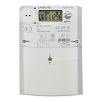
Elgama GAMA 100 User Manual (68 pages)
Static electricity meter
Brand:
Elgama
| Category:
Measuring Instruments
| Size: 4 MB
Table of Contents
Table of Contents
5
Contents
5
1 Safety
8
About this Document
8
Safety Requirements
8
Transportation and Storage Rules
8
Prevention and Elimination of Malfunctions
9
Exterior Inspection
9
Inspection of Connection and Parametrization Constants
9
Procedure of Meter Returning to Manufacturer
9
Proper Disposal of Product
9
2 Designation
10
3 Meter Modifications
11
Modifications
11
Technical Specifications
11
4 Functional Possibilities
12
Current, Voltage, Frequency
12
Additional Functions
13
Sealed Button Functions
13
Backup Power Source
14
Communication, Inputs/Outputs
14
Voltage and Current Circuit Separation
15
Internal Bi-Stable Mains Relay
15
LCD Options
15
Internal PLC Modem
15
5 Construction
16
Case
16
Nameplate
16
Terminal Block
17
Operation Principle
18
Measurement Module
18
Signal Conversion
18
Micro-Controller
18
Non-Volatile Memory
18
Display (LCD)
18
Default LCD (Option #1)
19
Optional LCD (Option #2)
20
Extended LCD (Option #3)
21
Internal Clock
22
Synchronization of Internal Clock (RTC)
22
Sliding Voltage Link
23
6 Communication
23
Optical Communication Interface
23
Electrical Interface
23
Controller MCL 5.XX with Internal GSM/GPRS Modem
24
PLC Modem
25
Internal PLC Modem
26
Wired M-Bus Module
26
Wireless M-Bus Interface
27
Plug & Play
27
Outputs/Inputs
27
Optical Test Output (Red LED)
27
S0 Outputs
27
Relay Output
27
Power Supply
28
Power Supply for External Modem
28
Push Buttons
28
Scroll Push Button and Optical Scroll Key
28
Sealed Push-Button
29
7 Data Registers
29
Energy Registers
29
Demand Registers
30
Maximum Demand Registers
31
8 Data Profiles
31
Billing Profile
31
Load Profile
33
Second Load Profile
34
Wired M-Bus Load Profile
34
Event Log
34
Power Failure (Outage) Event Log
35
Voltage Swell (Over-Voltage) Event Log
35
Voltage Sag (Under-Voltage) Event Log
35
Event Log of Internal Mains Relay
35
Power Over-Limit Event Log
36
Reverse Current Flow Event Log
36
Over-Current Event Log
36
Neutral Current Balance Event Log
37
Magnetic Field Influence Event Log
37
Opening of Meter Cover Event Log
37
Opening of Terminal Cover Event Log
37
Clock Change (Setting) Event Log
37
Parameterisation (Parameter Change) Event Log
38
Security Failure (Failed Authentication) Log
38
Meter (Internal) Error Event Log
39
Tariffs Event Log
39
Load Profiles Reset Log
39
Firmware Update Event Log
39
9 Data Monitors
39
Demand Monitor
39
Current Monitor
40
Over-Voltage Monitor
41
Under-Voltage Monitor
41
10 Tariff Program
42
Day Tariff Programs
42
Week Tariff Program
43
Tariff Seasons
43
List of Special Days
43
Emergency" Tariff
44
Tariff Timers
44
11 Data Reading
44
Reserved-Automatic (RA) Display Sequence
47
Main Automatic (MA) Display Sequence
48
Main Manual (MM) Display Sequence
48
Indication of Abnormal States on LCD
48
Internal Meter Errors
48
Data Reading Via Communication Interfaces
49
12 Parametrization
49
13 Data Protection
51
Physical Protection
51
Software Protection
51
Data Access Security
51
Passwords
51
Encryption and Authentication
52
Firmware/Hardware Identifiers
52
User's Identifiers
52
Blocking of Optical Communication Interface
52
Parameterization ID
53
Event Log, Security Alerts
53
Firmware Upgrade
53
14 Internal Bi-Stable Main Relay
54
Action "Disconnect by Remote Control Command
55
Action "Disconnect by Contractual Power Exceeded
55
Action "Disconnect by Phase Current Limit Exceeded
56
Action "Disconnect by Swings of Network Voltage
57
Action "Allow to Connect by Remote Control Command
58
Action "Allow to Connect by End of Billing Period
58
Action "Allow to Connect by End of Event
59
Action "Connect by Menu Button
59
Action "Connect by the Mains Switch of the Internal Electrical Installation
59
15 Installation
60
Annex A. Dimensions of the Meter
61
Annex B. Screw Torques Used in G1B Meters
62
Annex C. List of Data Objects
63
Advertisement
Elgama GAMA 100 User Manual (41 pages)
Single-Phase Static Meter
Brand:
Elgama
| Category:
Measuring Instruments
| Size: 4 MB
Table of Contents
Table of Contents
6
List of Tables
7
List of Figures
7
About this Document
8
Designation
9
Meter Variants
9
GAMA 100 Meter Constructions
9
Meter Possibilities
9
Additional Possibilities
9
Table 2-1 Type Designation
10
Table 2-2 Modifications
11
Technical Characteristics
12
Table 3-1 Technical Data
12
Construction
13
Meter Case
13
Figure 4-1 G1S Meter Exterior
13
Figure 4-2 G1E Meter Exterior
14
Figure 4-3 G1A Meter Exterior View (with Changeable Battery)
15
Table 4-1 Explanation of Figure 4-1- Figure 4-3
16
Figure 4-4 G1A Meter Exterior View (Without Changeable Battery)
16
Figure 4-5 G1S Meter Nameplate
17
Figure 4-6 G1E Meter Nameplate
18
Figure 4-7 G1A Meter Nameplate
18
Operation Principle
19
Measurement Module
19
Current Measurement in Neutral Circuit
19
Signal Conversion
19
Microcontroller
19
Figure 4-8 G1A Meter Nameplate
19
Non-Volatile Memory
20
Liquid Crystal Display (LCD)
20
Figure 4-9 Controlled Segments of G1E Meter's LCD
20
Figure 4-10 Controlled Segments of G1A Meter's LCD
21
Mechanical Register
22
Internal Clock (G1A)
22
Communication Interfaces
22
Optical Interface
22
Electrical Interface
22
Table 4-2 Possible Clock Adjustments for a Daylight Saving
22
Outputs and Inputs
23
Optical Test Output (Red LED)
23
S0 Outputs
23
Relay Output (Optional, Only G1A)
23
Tariff Switch Input (Optional, Only G1E)
23
Power Supply
23
Push Buttons (G1A)
23
Changeable Battery (Only G1A)
24
Sliding Voltage Link
25
Figure 4-11 a Sliding Voltage Link (Disconnected)
25
Tariff Module (G1A)
26
Tariff Programs
26
Table 5-1 Example of Day Profile
26
Table 5-2 Example of Week Profile
26
Special Day Calendar
27
Data Reading
28
Manual Data Scrolling on the LCD (G1A)
28
Table 6-1 List of Ways to Access Meter Data
28
Table 6-2 Meanings of Digits in Meter Configuration
28
Figure 6-1 Scrolling Cycle of Parameters
29
Table 6-3 Index Meanings Stated in LCD Indicator
30
Figure 6-2 Monthly Historical Billing Data Display Menu
30
Cyclic Data Scrolling
31
Energy Indication
31
Indication of Instantaneous Power (Only G1A)
31
Indication of Failures
31
Data Reading Via Communication Interfaces
32
Table 6-4 Data Read Via Communication Port and Its OBIS Codes (G1A)
32
Table 6-5 Data Read Via Communication Port and Its OBIS Codes (G1E)
33
Parameterisation
34
Prevention of Meter Data Modification
35
Means of Physical Prevention
35
Means of Software Prevention
35
Password (G1A)
35
Event Register (G1A)
35
Parameterization Lock (G1A)
35
Other Means of Prevention
35
Technical Service of Meter
36
Safety Rules
36
Prevention and Elimination of Malfunctions
36
Exterior Inspection
36
Inspection of Connection and Parameterization Constants
36
Transportation and Storage Rules
37
The Procedure of Returning to Manufacturer
37
Annex A. Connection of the Meter
38
Figure A-0-1 Connection Diagram of GAMA 100 (G1S) Meter
38
Figure A-0-2 Connection Diagram of GAMA 100 (G1E) Meters (with External Tariff Changeover Input)
38
Figure A-0-3 Connection Diagram of GAMA 100 (G1A) Meter (with One Current Measurement Circuit)
38
Figure A-0-4 Connection Diagram of GAMA 100 (G1A) Meter (with Current Measurement in Neutral)
39
Annex B. Dimensions of the Meter
40
Figure B-0-1 Dimensions of the GAMA 100 Series Meters
40
Annex C. Screw Torques Used in GAMA 100 Series Meters
41
Table C-0-1 Screw Torques Used in GAMA 100 Series Meters
41
Figure C-0-1 Screws Used in GAMA 100 Series Meters
41
Advertisement
Related Products
Elgama G1B Series
Elgama DC12U
Elgama EPQS
Elgama Categories
Measuring Instruments
More Elgama Manuals
Login
Sign In
OR
Sign in with Facebook
Sign in with Google
Upload manual
Upload from disk
Upload from URL