Sign In
Upload
Manuals
Brands
effeff Manuals
Controller
720-30
effeff 720-30 Manuals
Manuals and User Guides for effeff 720-30. We have
1
effeff 720-30 manual available for free PDF download: Operating And Installation Instructions
effeff 720-30 Operating And Installation Instructions (88 pages)
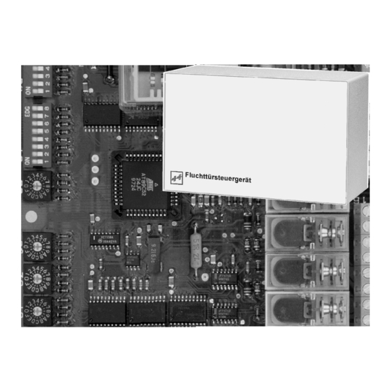
Emergency Exit Control Unit
Brand:
effeff
| Category:
Controller
| Size: 4 MB
Table of Contents
Deutsch
2
Table of Contents
2
1 Betrieb und Funktion
3
Fluchttürsteuergerät
3
Türterminal
4
D00192
4
Übersichtstabelle Betriebsanzeigen
5
Überwachungs- und Alarmfunktionen
6
Betätigung der Nottaste
6
Tür Offen Überwachung
6
Verriegelungsüberwachung
6
Sabotage der Tür
6
Sabotage am Türterminal, Terminal-Modul oder Bedienteil
6
Sabotage der Leitungen
6
Schaltfunktionen
7
Kurzzeitfreigabe
7
Dauerentriegelung
7
Verriegelung
7
Alarmrückstellung
7
Besonderheiten Beim Terminal-Modul 1370-10
8
Zerstörungsfreie / Zerstörende Betätigung des Notschalters
8
Öffnen der Abdeckhaube
8
Funktionsvarianten
9
Kurzzeitfreigabe
9
Dauerentriegelung
9
Voralarm
9
Alarm
9
Alarmzeit
9
Sonderfunktion I: Anlagen mit Indirekter Freischaltung. das Fluchttürsteuergerät 720-32
10
Sonderfunktion II: Betrieb des Fluchttürsteuergeräts mit dem Elektro-Sicherheitsschloß 809
11
Sonderfunktion III: Betrieb am Effeff-Türsteuerbus mit Steuerungstableau 925
12
Ermittlung einer Alarmbedingung
13
1.10 Beseitigung der Alarmursachen
14
2 Installation
15
Montage des Steuergeräts
16
Allgemeine Hinweise zur Elektrischen Installation
17
Kabelpläne und Anschlußdetails
18
Fluchttürsicherung für eine Einflügelige Fluchttür (Kabelplan)
18
Fluchttürsicherung für eine Zweiflügelige Fluchttür (Kabelplan)
19
Netz- und Akkuanschluß
20
Verriegelungssysteme mit dem Türterminal 1337-10/11
22
Anschlußdetail Paralleler Anschluß Bedienteil 1332 und Türterminal 1337-10/11
22
Anschlußdetail: Paralleler Anschluß von Zwei Türterminals 1337-10/11
23
Gesamtanschlußplan 720-30 mit Türterminal 1337-10/11
24
Verriegelungssysteme mit dem Terminal-Modul 1370-10
26
Anschlußdetail: Terminal-Modul 1370-10 mit Bedienteil 1332
26
Anschlußdetail Paralleler Anschluß Zweier Terminal-Module 1370-10
27
Gesamtanschlußplan 720-30 mit Terminal-Modul 1370-10
28
Anlagen mit Indirekter (Zentraler) Freischaltung (Sonderfunktion I)
30
Anschlußschema Indirekte (Zentrale) Freischaltung
31
Gesamtanschlußplan 720-32
32
Einstellschalter für Funktionen und Zeitabläufe
34
Werkseitige Stellung der Einstellschalter
34
Zeitvorgaben
35
S 5 Funktionsvarianten
35
S 6 Busadresse
36
S 7 Sonderfunktionen
36
Steuereingänge
37
Meldeausgänge
37
Anschluß von Brandmeldern (Klemmen 45-46)
38
Sonderfunktion II: Betrieb des Fluchttürsteuergeräts mit dem Elektrosicherheitsschloß 809
39
Sonderfunktion III Betrieb der Steuerung am Steuerungstableau 925 (Bus-Technologie)
40
Technische Daten
41
3 Inbetriebnahme, Wartung, Wiederkehrende Prüfung
42
Inbetriebnahme und Wiederkehrende Prüfung
42
Wartung
42
4 Checkliste zur Prüfung vor Erstinbetriebnahme
43
Operating and Installation Instructions
45
English
46
1 Operation and Functional Characteristics
47
Door Terminal and Terminal Module
48
Overview of Operating Displays
49
Monitoring and Alarm Functions
50
Actuating the Emergency Button
50
Door Open Monitoring
50
Locked Status Monitoring Function
50
Door Sabotage
50
Sabotage at the Door Terminal, Terminal Module or Control Unit
50
Sabotage to Cables
50
Switching Functions
51
Temporary Release
51
Permanent Unlocking
51
Locking
51
Alarm Reset
51
Function Variants
53
Temporary Release
53
Permanent Unlocking
53
Pre-Alarm
53
Alarm
53
Alarm Time
53
Special Function I: Systems with Indirect Release. the Emergency Exit Control Unit 720-32
54
Special Functions II: Operation of the Emergency Exit Control Unit Using Electrical Security Lock 809
55
Special Function III: Operation at the Effeff Door Control Bus with Control Panel 925
56
Determination of an Alarm Condition57
57
1.10 Eliminating the Reasons for the Alarm
58
2 Installation
59
Mounting the Control Unit
60
General Information on the Electrical Installation
61
Cable Diagrams and Connection Details
62
Emergency Exit Security System for a Single-Leaf Door (Cable Diagram)
62
Emergency Exit Security System for a Two-Leaf Emergency Exit (Cable Diagram)
63
Mains and Battery Connection
64
Locking Systems with the Door Terminal 1337-10/11
66
Connection Detail Parallel Connection Control Unit 1332 and Door Terminal 1337-10/11
66
Connection Detail: Parallel Connection of Two Door Terminals 1337-10/11
67
Locking Systems with Terminal Module 1370-10
70
Connection Detail: Terminal Module 1370-10 with Operator Terminal 1332
70
Connection Detail Parallel Connection of Two Terminal Modules 1370-10
71
Overall Terminal Diagram 720-30 with Terminal Module 1370-10
72
Systems with Indirect (Central) Release (Special Function I)
74
Terminal Diagram, Indirect (Central) Release
75
Overall Terminal Diagram 720-32
76
Setting Switches for Functions and Time Sequences
78
Time Inputs
79
S 5 Function Variants
79
S 6 Bus Address
80
S 7 Special Functions
80
Control Inputs
81
Signal Outputs
81
Connection of Fire Alarm Systems (Terminals 45-46)
82
Special Function II: Operation of the Emergency Exit Control Unit with the Electrical Security Lock 809
83
Special Function III Operation of the Control System at Control Panel 925 (Bus Technology)
84
Specifications
85
3 Commissioning, Maintenance, Recurring Tests
86
Commissioning and Recurring Tests
86
Maintenance
86
4 Checklist for Testing Prior to Initial Commissioning
87
Advertisement
Advertisement
Related Products
effeff 720-32
effeff Categories
Locks
Door locks
Control Unit
Touch terminals
Controller
More effeff Manuals
Login
Sign In
OR
Sign in with Facebook
Sign in with Google
Upload manual
Upload from disk
Upload from URL