Sign In
Upload
Manuals
Brands
eddyfi Manuals
Security Sensors
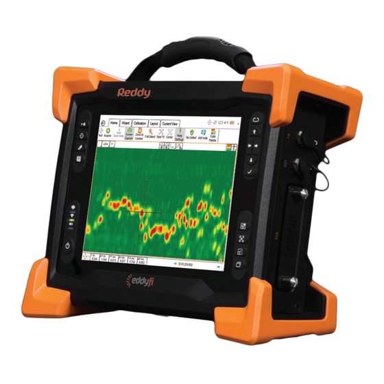
Reddy
eddyfi Reddy Manuals
Manuals and User Guides for eddyfi Reddy. We have
1
eddyfi Reddy manual available for free PDF download: User Manual
eddyfi Reddy User Manual (82 pages)
Brand:
eddyfi
| Category:
Security Sensors
| Size: 5 MB
Table of Contents
Table of Contents
3
General Precautions and Conventions
10
General Precautions
10
Safety Precautions
11
Conventions
12
EMC Directive Compliance
13
Calibration and Warranty Seals
13
Limited Warranty
14
Copyrights
14
Chapter 1 Reddy Overview
16
Introducing Reddy
17
Positioning Reddy
22
Figure 1-1 Reddy in the Horizontal Position
22
Figure 1-2 Reddy in the Tilted Position
22
Starting Reddy
23
Shutting down Reddy
23
Figure 1-3 Shutting down Reddy
23
Connecting Probes
24
Batteries
24
Figure 1-4 Optional Battery Charger
26
Chapter 2 Magnifi GO Overview
28
Introducing Magnifi ® GO
29
Figure 2-1 Front-Stage View
30
Figure 2-2 Strip Chart
31
Figure 2-3 Lissajous
31
Figure 2-4 C-Scan
32
Table 2-1 Multi-Touch Behavior in the Strip Chart View
32
Table 2-2 Multi-Touch Behavior in the Lissajous View
32
Figure 2-5 Project
33
Table 2-3 Multi-Touch Behavior in the C-Scan View
33
Figure 2-6 Acquisition Summary
34
Figure 2-7 Report Summary
34
Figure 2-8 Save
35
Figure 2-9 Material Database
35
Chapter 3 Preferences
36
Managing Preferences
37
Figure 3-1 General Preferences
37
Figure 3-2 Display Preferences
37
Figure 3-3 Analysis Preferences
38
Figure 3-4 Help
38
Chapter 4 Keypad and Keyboard Functions
40
Keyboard Shortcut Keys
41
Table 4-1 Keyboard Shortcut Keys
41
Chapter 5 Using Reddy with Sharck Probes
42
Introduction
43
Figure 5-1 Medium Shark Probe
43
Figure 5-2 Removable Sharck Encoder and Guiding Wheels
43
Tangential Eddy Current Array Technology
44
Figure 5-3 Simplified TECA Working Principles
44
Figure 5-4 Typical Signal Signature
44
Figure 5-5 Effects of Compensation to Liftoff on Detected 5 MM Deep Defect with 0, 1, 2 MM Liftoffs
44
Figure 5-6 Integrated 3D Depth Plane to Correlate Crack Depth, Vertical Amplitude, and Liftoff
45
Figure 5-7 Example Data Before/After Adjusting User Mat
45
Getting Ready
46
Figure 5-8 Backstage View: Create/Open Inspection
46
Figure 5-9 Creating an Inspection Project
46
Figure 5-10 Acquisition Summary Dialog Box
47
Figure 5-11 Backstage View: Create/Open Setup
47
Setting up Your Inspection
48
Figure 5-12 Open Setup Dialog Box
48
Figure 5-13 Verifying the Applied Setup
48
Figure 5-14 Component Definition
49
Figure 5-15 Probe Selection
49
Figure 5-16 Scan Definition: Configure Scan
49
Figure 5-17 Scan Definition: Configure Encoder and Start Position
50
Figure 5-18 Data Definition: Configuring Filters
50
Figure 5-19 Indication Codes
51
Figure 5-20 Display Properties
51
Figure 5-21 Display Layout
51
Figure 5-22 Nulling the Sharck Probe
52
Figure 5-23 Sharck Assisted Calibration
52
Figure 5-24 Sharck Assisted Calibration: Calibration Complete
53
Figure 5-25 Sharck Probe on Carbon Steel Weld
54
Figure 5-26 Probe Origin and Defect Positioning Along the Scanning Axis (Probe Shown Top View)
54
Figure 5-27 Disabled Functions During Acquisition
55
Figure 5-28 Saving Data
55
Analyzing Data
56
Figure 5-29 Flaw-Like and Spurious Indications
56
Figure 5-30 Sizing Information
57
Figure 5-31 Take Screen Captures with Defect Report Entry Check Box
57
Figure 5-32 Selecting a Layout
57
Figure 5-33 Entering a Detected Defect
58
Figure 5-34 Measurement Methods
58
Figure 5-35 Report Tab
59
Figure 5-36 Transverse C-Scan
59
Saving and Reporting
60
Figure 5-37 Report Summary
60
Figure 5-38 Report Options
60
Figure 5-39 Report Summary
61
Figure 5-40 Inspection Report
61
Chapter 6 Maintenance and Troubleshooting
62
Maintaining Reddy
63
Updating and Upgrading Magnifi ® GO
63
Figure 6-1 Options Menu
64
Figure 6-2 System Recovery Interface
64
Troubleshooting
65
Chapter 7 Specifications
66
General
67
Environmental
67
Eca
67
Table 7-1 General Specifications
67
Table 7-2 Environmental Specifications
67
Table 7-3 Eddy Current Array Specifications
67
Ect
68
Table 7-4 Eddy Current Testing Specifications
68
Appendix A Connector Reference
70
ECA Connector (160 Pins)
71
ECT Connector (19 Pins)
71
I/O Connector (12 Pins)
71
Table A-1 ECT Connector Data
71
Table A-2 ECT Connector Pinout
71
Table A-3 I/O Connector Data
71
Ethernet Connector
72
HDMI Connector
72
Table A-4 I/O Connector Pinout
72
Table A-5 Ethernet Connector Data
72
Table A-6 Ethernet Connector Pinout
72
Table A-7 HDMI Connector Data
72
USB Connectors
73
3.5 MM Audio Connector
73
Table A-8 HDMI Connector Pinout
73
Table A-9 USB Connector Data
73
Table A-10 USB Connector Pinout
73
Table A-11 Audio Connector Data
73
Table A-12 Audio Connector Pinout
73
Appendix B Using the Optional Harness
74
Adjusting the Harness
75
Figure B-1 Slipping the Harness on
75
Figure B-2 Adjusting the Shoulder Straps
76
Figure B-3 Adjusting the Belt's Height
76
Figure B-4 Securing the Chest Straps
76
Figure B-5 Securing the Belt
77
Figure B-6 Shoulder Anchor Straps
77
Figure B-7 Unfastening the Straps
78
Figure B-8 Sliding Strap Loop through Bumper Hook
78
Figure B-9 Securing Anchor Strap
78
Figure B-10 Alternative Method of Securing Anchor Strap to Bumper
79
Figure B-11 Anchor Strap on Harness Belt
79
Figure B-12 Slipping Male Buckle through Bumper
79
Figure B-13 Mating Battery Compartment Side Anchor Strap
80
Figure B-14 Closing Battery Compartment Door
80
Figure B-15 Mating Shoulder Anchor Strap
80
Figure B-16 Tightening Shoulder Anchor Straps
81
Figure B-17 Belt-Slinging Probe Cable
81
Advertisement
Advertisement
Related Products
eddyfi R-Scan Array
eddyfi Categories
Measuring Instruments
Analytical Instruments
Diagnostic Equipment
Security Sensors
More eddyfi Manuals
Login
Sign In
OR
Sign in with Facebook
Sign in with Google
Upload manual
Upload from disk
Upload from URL