Sign In
Upload
Manuals
Brands
Ecolab Manuals
Water Pump
Elados EMP II E60
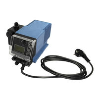
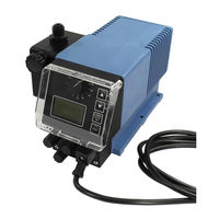
Ecolab Elados EMP II E60 Metering Pump Manuals
Manuals and User Guides for Ecolab Elados EMP II E60 Metering Pump. We have
2
Ecolab Elados EMP II E60 Metering Pump manuals available for free PDF download: Operating Instruction, Short Operating Instructions
Ecolab Elados EMP II E60 Operating Instruction (218 pages)
Brand:
Ecolab
| Category:
Water Pump
| Size: 24 MB
Table of Contents
Deutsch
2
Table of Contents
2
1 Allgemeines
5
EBS Nummernreihe
5
Transportschäden
5
Gewährleistungsumfang
5
Kontaktadresse / Hersteller
5
2 Sicherheit
6
Sicherheitshinweise
6
Hervorhebungen
6
Aufzählungen
6
Spezielle Sicherheitshinweise bei Wartungs- und Reparaturarbeiten
6
3 Lieferumfang
7
Zubehör zu Aufrüstung auf EMP II E60
7
Plus
7
4 Funktionsbeschreibung
8
Mechanische Funktionen
8
Elektronische Funktionen
8
Betriebsarten
8
Elektronische Zusatzfunktionen bei EMP II E60
8
Plus
8
5 Aufbau
9
Emp II E60
9
Emp II E60 Plus
9
Anzeigen / Bedienelemente / Anschlussbuchsen
9
Ausführung EMP II E60 und EMP II E60
9
Plus
9
Anschlussbuchsen „Dongle-Box
9
6 Einbau
10
Einbauschema
10
7 Geräteinstallation
11
Hydraulische Installation
11
Installationsbeispiele
11
Anschluss der Saug- und Druckleitung
13
Elektrische Installation
13
Ein- und Ausgänge
13
Anschlussbelegung Steckplatz I (3-Polig) Eingang für Niveauvorwarnung und Leermeldung
13
Installation Sauglanze mit Niveauvorwarnung und Leermeldung
14
Anschluss Steckplatz II (5-Polig) Eingang für Impuls-, Normsignal, Dosiersperre, Charge und Dosierüberwachung
14
Installation für Impulsansteuerung (Wasserzähler)
14
Installation für Normsignal Ansteuerung
15
Installation Ansteuerung über Dosiersperre
15
Installation Chargenfunktion
15
Installation Dosierüberwachung
16
Anschlussbelegung Steckplatz III (4-Polig), Ausgang für Alarm und Hubsignal
16
Installation Niveau- Bzw. Störmeldeausgang
17
Installation Hubsignalausgang bei 24 V / DC
17
Hardwareumstellung für den Alarmkontakt
17
Bei Konfigurationseinstellung Alarmausgang "EIN
18
Bei Konfigurationseinstellung Alarmausgang "AUS
18
Anschlussbelegung Steckplatz IV, Netzanschluss
18
8 Aufrüstung der EMP II E60 auf EMP II E60
19
Plus
19
Montage von Dongle- Box Bzw. Microflow- Box
19
Anschlussbelegung der Steckplätze
20
Anschlussbelegung Steckplatz V (5-Polig), Dongle- Box
20
Installation Ovalradzähler OGM PLUS
20
Anschlussbelegung Steckplatz V, Microflow- Box
20
Installation Microflow Meßwertaufnehmer
21
Anschlussbelegung Steckplatz VII (5-Polig) Eingang für Chargenimpuls und Dosiersperre
21
Installation Chargenimpuls
22
Installation Dosiersperre (Wahlweise Anschluss VII oder VIII)
22
Anschlussbelegung Steckplatz VIII (5-Polig) Eingang für Impuls, Normsignaleingang und Dosiersperre
23
Installation für Impulsansteuerung (Wasserzähler)
23
Installation Normsignal (Ma)
23
Installation Dosiersperre
23
9 Inbetriebnahme
24
Ein- Ausschalten der Pumpe
24
Einstellen der Dosierleistung (Mechanisch)
24
Entlüftung der Dosierpumpe
24
Tastenfunktionen
25
Displayanzeigen
25
Anzeige der Softwareversion
25
Auslieferzustand
26
Grundeinstellung der Betriebsart / Anzeige in der Betriebsebene
26
Grundeinstellungen in der Konfiguration
26
10 Menübeschreibung
27
Hauptmenü
27
Übersicht
27
Betriebsart
27
Auswählen
27
Betriebsart / Intern
28
Auswählen
28
Displayanzeige in der Betriebsebene / Einstellen
29
Betriebsart / Impuls
29
Auswählen
30
Displayanzeige in der Betriebsebene / Einstellen
30
Betriebsart / Strom (Extern-Normsignal)
30
Auswählen
31
Einstellen Betriebsart / Strom / Beliebig
31
Displayanzeige in der Betriebsebene
32
Konfiguration
32
Übersicht
32
Display-Rollen
32
Konfiguration / Sprache
32
Auswählen
33
Konfiguration / Einheit
33
Konfiguration / Code
33
Einstellen
34
Konfiguration / Autostart
34
Auswählen
34
Konfiguration / Dosiersperre
34
Konfiguration / Niveaukontakt
35
Auswählen
35
Konfiguration / Alarmausgang
35
Umstellung Funktionsweise Alarmrelais Kontakt
35
10.3.10 Konfiguration / Impulsspeicher
35
Auswählen
36
10.3.10.2 Displayanzeige in der Betriebsebene bei Aktiviertem Impulsspeicher
36
Konfiguration / Ovalradzähler (nur E60 PL US & OGM PLUS )
36
10.3.11.1 Auswählen
37
Konfiguration / Dosierregler (nur E60 PLUS & OGM PLUS )
37
10.3.12.2 Displayanzeige in der Betriebsebene bei Aktiviertem Dosierregler
38
10.3.13 Konfiguration / Dosierüberwachung
38
10.3.13.1 Auswählen
38
10.3.13.2 Dosierüberwachung / Pumpe Stoppen
39
10.3.13.3 Dosierüberwachung / Hübe
39
Dosierüberwachung / Abweichung (nur bei E60 PLUS & OGM Bzw. OGM PLUS )
39
Dosierüberwachung / Eingang (nur bei E60 ohne Dongle-Box)
40
Anzeige der Ovalradzähler- Impulse (nur E60 PLUS )
40
Konfiguration / Microflow
40
Plus
40
10.3.14.1 Auswählen
41
Microflow PLUS / Pumpe Stoppen
41
Microflow PLUS / Hübe
41
Microflow PLUS / Abweichung
42
Microflow PLUS / Dosierpause
42
Microflow PLUS / Dosierverzögerung
43
Microflow PLUS / Kalibrierung
43
Konfiguration / Charge
43
10.3.15.1 Auswählen
44
10.3.15.2 Charge / Menge
44
Charge / Eingang (nur bei E60 ohne Dongle-Box)
45
10.3.15.4 Displayanzeige in der Betriebsebene
45
Konfiguration Degas PLUS
45
10.3.16.1 Auswählen
45
Degas PLUS / Degas Hübe
46
Degas PLUS / Degas Pause
46
Kalibrierung
46
Übersicht
46
Kalibrierung / Pumpe
47
Vorbereitung
47
Kalibrierung / Starten
47
Kalibrierung / Pumpe mit Ovalradzähler (OGMP LUS )
47
Vorbereitung
48
Kalibrierung / Starten
48
Kalibrierung / Manuell
49
Tabelle Kalibrierdaten
49
Betriebsdaten
49
Übersicht
50
Betriebsdaten / Betriebsstunden
50
Auswählen / Anzeigen / Löschen
50
Betriebskosten / Liter
50
Betriebsdaten / Impulsanzahl
51
Auswählen / Anzeigen / Löschen
51
11 Wartung
52
Austausch von Saug- / Druckventil und Dosierpatronen
52
Kugel-Ventil (V3), 1,4 - 2,5 L/H für Typ: V3014 - V3025
52
Kugel-Ventile
53
Dosierventile Lagerichtig Einbauen
53
Wechsel der Ventilpatronen, Typ V3
53
Austausch der Membrane und des Pumpenkopfes
54
Justierung der Mechanischen Hubverstellung
54
12 Betriebsstörungen
55
Warmeldungen Dosierung (Display)
55
Alarmmeldungen (Display)
55
Ogm Plus
56
P LUS in der Pumpensoftware
56
Störungssuche
56
13 Verschleiß- und Ersatzteile (Standard-Ausführung)
57
Explosionszeichnung / Stückliste Typ V3014, V3025, 00043, 00048, 00072 und Typ 00112
57
Verschleißteilset Typ V3014, V3025, 00043, 00048, 00072 und Typ 00112
58
Pumpenkopf - Servicesatz „Höhere Drücke" (1,6 Mpa / 16 Bar)
58
Explosionszeichnung / Stückliste Typ 00240
59
Verschleißteilset Typ 00240
59
14 Technische Daten
60
Pumpenschlüssel
60
Pumpenschlüssel 1
60
Pumpenschlüssel 2
61
Pumpenschlüsseldefinition
62
Abmessungen
63
Typ V3014, V3025, 00043, 00048, 00072 und Typ 00112
63
Typ 00240
63
Technische Daten „Übersichtstabellen
64
Allgemeine Daten Standardpumpen
64
Abweichende Allgemeine Daten Pumpen der Version „Höhere Drücke (HP)
64
Werkstoffe
64
Ein- / Ausgangsbeschaltung
65
Steckplatz I
65
Steckplatz II
65
Steckplatz III
65
Anschlussstecker / Steuer Ein- und Ausgänge
66
Pinbelegung / Aderfarben Stecker I (3-Polig)
66
Pinbelegung / Aderfarben Stecker II (5-Polig)
66
Pinbelegung / Aderfarben Stecker III (4-Polig)
66
Dosierleistungen
66
Förderleistungen in Abhängigkeit von Gegendruck und Hubeinstellung
67
Förderleistung Typ V3014 / 1 Mpa (10 Bar)
67
Förderleistung Typ V3014 / 1,6 Mpa (16 Bar) / (Sonderversion: Höhere Drücke)
67
Förderleistung Typ V3025 / 1 Mpa (10 Bar)
68
Förderleistung Typ V3025 / 1,6 Mpa (16 Bar) / (Sonderversion: Höhere Drücke)
68
Förderleistung Typ 00043 / 1 Mpa (10 Bar)
69
Förderleistung Typ 00043 / 1,6 Mpa (16 Bar) / (Sonderversion: Höhere Drücke)
69
Förderleistung Typ 00048 / 0,4 Mpa (4 Bar)
70
Förderleistung Typ 00072 / 0,6 Mpa (6 Bar)
70
Förderleistung Typ 00072 / 1 Mpa (10 Bar)
71
Förderleistung Typ 00112 / 0,5 Mpa (5 Bar)
71
Förderleistung Typ 00240/ 0,2 Mpa (2 Bar)
72
15 Konformitätserklärung
73
English
74
1 General
77
EBS Numbers
77
Transport Damage
77
Warranty Coverage
77
Contact Address / Manufacturer
77
2 Safety
78
Safety Notes
78
Emphases
78
Enumerations
78
Special Safety Notes for Maintenance and Repair Work
78
3 Delivery Scope
79
Upgrade Accessories for the EMP II E60
79
Plus
79
4 Functional Description
80
Mechanical Functions
80
Electronic Functions
80
Operation Modes
80
Additional Electronic Functions on the EMP II E60
80
Plus
80
5 Setup
81
Emp II E60
81
Emp II E60 Plus
81
Indicators / Controls / Jacks
81
Versions EMP II E60 and EMP II E60
81
Plus
81
Dongle Box" Ports
81
6 Mounting
82
Mounting Diagram
82
7 Device Installation
83
Hydraulic Installation
83
Installation Examples
83
Connecting the Suction Pipe and Pressure Pipe
85
Electrical Installation
85
Inputs and Outputs
85
Connector Assignments of Slot I (3-Terminal) Input for Low-Level Advance Warning and Empty Report
85
Installing the Suction Pipe with Low-Level Advance Warning and Empty Report
86
Connector Assignment of Slot II (5-Terminal) Input for Pulse Signal, Standard Signal, Metering Lock, Batch and Metering Monitoring
86
Installing the Pulse Control (Water Meter)
86
Installing the Standard Signal Control
87
Installing the Control Via the Metering Lock
87
Installing the Batch Function
87
Installing the Metering Monitoring
88
Connector Assignments of Slot III (4-Terminal) Output for Alarm and Stroke Signal
88
Installing the Alarm or Fault Report Output
89
Installing the Stroke Signal Output at 24 V / DC
89
Hardware Migration for Alarm Contact
89
In the Alarm Output "ON" Configuration Setting
90
In the Alarm Output "OFF" Configuration Setting
90
Connector Assignments of Slot IV, Mains Power Supply
90
Plus
91
Fitting of the Dongle Box Respectively the Microflow-Box
91
Connector Assignments of the Slots
92
Connector Assignments of Slot V (5-Terminal), Dongle-Box
92
Installing the Oval Gear Meter OGM
92
Plus
92
Connector Assignments of Slot V, Microflow- Box
92
Installation Microflow Transducer
93
Connector Assignments of Slot VII (5-Terminal) Input for Batch Pulse and Metering Lock
93
Installing the Batch Pulse
94
Installing the Metering Lock (Optional Connector VII or VIII)
94
Connector Assignments of Slot VIII (5-Terminal) Input for Pulse, Standard Signal Input and Metering Lock
95
Installing the Pulse Control (Water Meter)
95
Installing the Standard Signal (Ma)
95
Installing the Metering Lock
95
8 Upgrading the EMPII E60 to the EMPII E60
91
9 Startup
96
Switching the Pump On/Off
96
Setting of the Metering Output (Mechanical)
96
Venting the Metering Pump
96
Key Functions
97
Description of Display Symbols
97
Software Version Display
97
Delivery Condition
98
Basic Setting of the Mode of Operation / Display in the Operating Display
98
Basic Settings in the Configuration
98
10 Menu Description
99
Main Menu
99
Overview
99
Operation Mode
99
Selecting
99
Operation Mode / Internal
100
Selecting
100
Display in the Operating Display/ Setting
101
Operation Mode / Pulse
101
Selecting
102
Display in the Operating Display / Setting
102
Operation Mode / Current (External Standard Signal)
102
Selecting
103
Setting Operation Mode / Current / User Defined
103
Display in the Operating Display
104
Configuration
104
Overview
104
Scrolling the Display
104
Configuration / Language
104
Selecting
105
Configuration / Unit
105
Configuration / Code
105
Setting
106
Configuration / Autostart
106
Selecting
106
Configuration / Metering Lock
106
Configuration / Low-Level Contact
107
Selecting
107
Configuration / Alarm Output
107
Conversion from Alarm Relay Mode to Contact Mode
107
10.3.10 Configuration / Pulse Memory
107
Selecting
108
10.3.10.2 Display in the Operating Display with an Active Pulse Memory
108
Configuration / Oval Gear Meter
108
Plus )
108
10.3.11.1 Selecting
109
Configuration / Metering Controller
109
Plus & Ogm Plus )
109
10.3.12.2 Display in the Operating Display with an Active Metering Controller
110
10.3.13 Configuration / Metering Monitoring
110
10.3.13.1 Selecting
110
10.3.13.2 Metering Monitoring / Stop Pump
111
10.3.13.3 Metering Monitoring / Strokes
111
Metering Monitoring / Deviation
111
Plus )
111
Metering Monitoring / Input (Only at E60 WITHOUT Dongle Box)
112
Oval Gear Meter Pulse Display
112
Plus )
112
Configuration / Microflow
112
10.3.14.1 Selecting
113
Microflow PLUS / Stop Pump
113
Microflow PLUS / Strokes
113
Microflow PLUS / Deviation
114
Microflow PLUS / Metering Break
114
Microflow PLUS / Metering Delay
115
Microflow PLUS / Calibration
115
10.3.15 Configuration / Batch
115
10.3.15.1 Selecting
116
10.3.15.2 Batch / Quantity
116
Batch / Input (Only at E60 WITHOUT Dongle-Box)
117
10.3.15.4 Display in the Operating Display
117
Configuration Degas
117
10.3.16.1 Selecting
117
Degas PLUS / Degas Strokes
118
Degas PLUS / Degas Break
118
Calibration
118
Overview
118
Calibration / Pump
119
Preparation
119
Calibration / Start
119
Calibration / Pump with Oval Gear Meter
119
Plus )
119
Calibration / Pump with Oval Gear Meter
120
Calibration / Start
120
Calibration / Manual
121
Calibration Data Table
121
Operating Data
121
Overview
122
Operating Data / Operating Hours
122
Selecting / Displaying / Deleting
122
Operating Data / Litre
122
Operating Data / Amount of Pulses
123
Selecting / Displaying / Deleting
123
11 Maintenance
124
Replacing the Suction / Pressure Valve and Metering Cartridges
124
Ball-Valve (V3), 1,4 - 2,5 L/H for Type: V3014 - V3025
124
Ball-Valves
125
Inserting the Metering Valves in the Correct Positions
125
Changing the Valve Cartridges, Type V3
125
Replacing the Diaphragm and Pump Head
126
Aligning the Mechanical Stroke Adjustment
126
12 Operating Faults
127
Metering Warning Messages (Display)
127
Alarm Messages (Display)
127
Deactivating of Dongle Box, OGM
128
PLUS in the Pump Software
128
Trouble Shooting
128
13 Wearing Parts and Spare Parts (Standard Version)
129
Exploded Drawing / List of Parts Type V3014, V3025, 00043, 00048, 00072 and Type 00112
129
Wearing Part Set Types V3014, V3025, 00043, 00048, 00072 and Type 00112
130
Pump Head - Service Set "Higher Pressure" (1.6 Mpa / 16 Bar)
130
Exploded Drawing / List of Parts, Type 00240
131
Wearing Part Set - Type 00240
131
14 Technical Specifications
132
Pump Keys
132
Pump Key 1
132
Pump Key 2
133
Pump Key Definition
134
Dimensions
135
Type V3014, V3025, 00043, 00048, 00072 and Type 00112
135
Type 00240
135
Technical Specifications "Overview Tables
136
General Data - Standard Pumps
136
Deviant General Data - Pumps in the "Higher Pressures (HP)" Version
136
Materials
136
In-/ and Output Circuit
137
Connector I
137
Connector II
137
Connector III
138
Connector Assignments
138
Pin Assignment / Conductor Coloring Connector I (3-Terminal)
138
Pin Assignment / Conductor Coloring Connector II (5-Terminal)
138
Pin Assignment / Conductor Coloring Connector III (4-Terminal)
138
Metering Rates
138
Delivery Capacity Depending on the Backpressure and Stroke Setting
139
Delivery Capacity Type V3014 / 1 Mpa (10 Bar)
139
Delivery Capacity Type V3014 / 1,6 Mpa (16 Bar) (Special Version: Higher Pressures)
139
Delivery Capacity Type V3025 / 1 Mpa (10 Bar)
140
Delivery Capacity Type V3025 / 1,6 Mpa (16 Bar) (Special Version: Higher Pressures)
140
Delivery Capacity Type 00043 / 1 Mpa (10 Bar)
141
Delivery Capacity Type 00043 / 1,6 Mpa (16 Bar) / (Special Version: Higher Pressures)
141
Delivery Capacity Type 00048 / 0,4 Mpa (4 Bar)
142
Delivery Capacity Type 00072 / 0,6 Mpa (6 Bar)
142
Delivery Capacity Type 00072 / 1 Mpa (10 Bar)
143
Delivery Capacity Type 00112 / 0,5 Mpa (5 Bar)
143
Delivery Capacity Type 00240 / 0,2 Mpa (2 Bar)
144
15 Declaration of Conformity
145
Français
146
1 Généralités
149
Numéros- EBS
149
Dommages Pendant Le Transport
149
Etendue de la Garantie
149
Contact / Adresse du Fabricant
149
2 Sécurité
150
Instructions de Sécurité
150
Passages Mis en Évidence
150
Énumérations
150
Instructions de Sécurité Spéciales Lors des Travaux de Maintenance Et de Réparation
150
3 Contenu de la Livraison
151
Accessoires Pour la Conversion Sur Le Modèle EMP II E60
151
Plus
151
4 Description du Fonctionnement
152
Fonctions Mécaniques
152
Fonctions Électroniques
152
Modes de Service
152
Fonctions Électroniques Supplémentaires Dans L' EMP II E60
152
Plus
152
5 Structure
153
Emp II E60
153
Afficheurs / Eléments de Commande / Prises de Connexion
153
Modèles EMP II E60 Et EMP II E60
153
Plus
153
Prises de Connexion du "Dongle-Box
153
6 Montage
154
Schéma de Montage
154
7 Installation de L'appareil
155
Installation Hydraulique
155
Exemples D'installation
155
Raccordement de la Conduite D'aspiration Et de la Conduite de Pression
157
Installation D'électrique
157
Entrées Et Sorties
157
Affectation des Connexions - Emplacement Enfichable I (À 3 Broches) Entrée du Pré-Avertissement de Niveau Et de la Signalisation de L'état Vide
157
Installation de la Lance D'aspiration Avec Pré-Avertissement de Niveau Et Signalisation D'état Vide
158
Affectation des Connexions - Emplacement Enfichable II (À 5 Broches) Entrée du Signal D'impulsion, du Signal Normalisé, du Blocage du Dosage, de la Charge Et de la Surveillance du Dosage
158
Installation de la Commande D'impulsion (Compteur D'eau)
158
Installation de la Commande du Signal Normalisé
159
Installation de la Commande Via Le Blocage du Dosage
159
Installation de la Fonction de Charge
159
Installation de la Contrôle du Dosage
160
Affectation des Connexions - Emplacement Enfichable III (À 4 Broches) - Sortie de L'alarme Et du Signal de Course
160
Installation de la Sortie Niveau Et Défaut Respectivement
161
Installation de la Sortie du Signal de Course Pour 24 V / DC
161
Conversion du Matériel Pour Le Contact D'alarme
161
Avec Le Réglage de Configuration - Sortie D'alarme " on
162
Avec Le Réglage de Configuration - Sortie D'alarme " off
162
Affectation des Connexions - Emplacement Enfichable IV, Connexion Au Réseau
162
Plus
163
Montage du Dongle-Box Ou Microflow- Box
163
Affectation des Connexions des Emplacements Enfichables
164
Affectation des Connexions - Emplacement Enfichable V (À 5 Broches), Dongle-Box
164
Installation du Compteur À Roues Ovales OGM
164
Plus
164
Affectation des Connexions - Emplacement Enfichable V, Microflow- Box
164
Installation D'enregistreur de Valeurs de Mesure Microflow
165
Affectation des Connexions - Emplacement Enfichable VII (À 5 Broches) Entrée de L'impulsion de Charge Et du Blocage du Dosage
165
Installation Pour L'impulsion de Charge
166
Installation du Blocage du Dosage (Au Choix Douille À Fiche VII Ou VIII)
166
Affectation des Connexions - Emplacement Enfichable VIII (À 5 Broches) Entrée de L'impulsion de Charge Et du Blocage du Dosage
167
Installation de la Commande D'impulsion (Compteur D'eau)
167
Installation du Signal Normalisé (Ma)
167
Installation du Blocage du Dosage
167
8 Conversion de L'empii E60 Sur L'empii E60
163
9 Mise en Service
168
Mise en Marche / Arrêt de la Pompe
168
Réglage de la Capacité de Dosage (Mécanique)
168
Purge de la Pompe Doseuse
168
Fonctions des Touches
169
Symboles Affichés
169
Affichage de la Version du Logiciel
169
État À la Livraison
170
Réglage de Base du Mode D'operation / Affichage Dans Le Niveau de Fonctionnement
170
Configuration
170
10 Description des Menus
171
Menu Principal
171
Vue D'ensemble
171
Mode Opération
171
Sélectionner
171
Mode Opération / Interne
172
Sélectionner
172
Affichage À L'écran Dans L'indicateur de Progression de L'appel / Réglage
173
Mode Opération / Impulsions
173
Sélectionner
174
Affichage À L'écran Dans L'indicateur de Progression de L'appel / Réglage
174
Mode Opération / Courant (Signal Normalisé Externe)
174
Sélectionner
175
Réglage Mode Opération / Courant / Choix Par Opérateur
175
Affichage Dans L'indicateur de Progression de L'appel
176
Configuration
176
Vue D'ensemble
176
Défilement de L'afficheur
176
Configuration / Langue
176
Sélectionner
177
Configuration / Unité
177
Configuration / Code
177
Réglage
178
Configuration / Démarrage Auto
178
Sélectionner
178
Configuration / Blocage du Dosage
178
Configuration / Commutateur D'niveau
179
Sélectionner
179
Configuration / Alarme
179
Réglage du Fonctionnement du Contact du Relais D'alarme
179
10.3.10 Configuration / Mémoire D'impulsions
179
Sélectionner
180
Affichage Dans L'indicateur de Progression de L'appel Lorsque la Mémoire D'impulsions Est Activée
180
Configuration / Compteur À Roues Ovales
180
Plus & Ogm Plus )
180
10.3.11.1 Sélectionner
181
Configuration / Réglage du Dosage
181
Plus & Ogm Plus )
181
Affichage Dans L'indicateur de Progression de L'appel Lorsque Le Régulateur de Dosage Est Activé
182
10.3.13 Configuration / Contrôle du Dosage
182
10.3.13.1 Sélectionner
182
10.3.13.2 Contrôle du Dosage / Arrêt Pompe
183
10.3.13.3 Contrôle du Dosage / Courses
183
Contrôle du Dosage / Écart
183
Plus )
183
Contrôle du Dosage / Entrée Blocage Dosage (Seulement Pour E60 SANS Dongle-Box)
184
Affichage des Impulsions du Compteur À Roue Ovale
184
Plus )
184
Configuration / Microflow
184
10.3.14.1 Sélectionner
185
Microflow PLUS / Arrêt Pompe
185
Microflow PLUS / Courses
185
Microflow PLUS / Écart
186
Microflow PLUS / Pause de Dosage
186
Microflow PLUS / Retard de Dosage
187
Microflow PLUS / Étalonnage
187
10.3.15 Configuration / Charge
187
10.3.15.1 Sélectionner
188
10.3.15.2 Charge / Quantité
188
Charge / Entrée (Seulement Pour E60 SANS Dongle-Box)
189
10.3.15.4 Affichage Dans L'indicateur de Progression de L'appel
189
Configuration Degas
189
Sélectionner
189
Degas PLUS / Degas Courses
190
Degas PLUS / Degas Pause
190
Étalonnage
190
Vue D'ensemble
190
Étalonnage / Pompe
191
Préparation
191
Étalonnage / Démarrage
191
Étalonnage / Pompe Avec Compteur À Roues Ovales
191
P Lu S )
191
Préparation
192
Étalonnage / Démarrage
192
Étalonnage / Manuel
193
Tableau des Données de Calibrage
193
Données D'opération
193
Vue D'ensemble
194
Données D'opération / Heures D'opération
194
Sélectionner / Afficher / Annuler
194
Données D'opération / Litres
194
Donées D'opération / Nombre D'impulsions
195
Sélectionner / Afficher / Annuler
195
11 Maintenance
196
Remplacement de la Soupape D'aspiration/De Pression Et des Cartouches de Dosage
196
Globuleux-Soupape (V3), 1.4 - 2.5 L/H Pour Type: V3014 - V3025
196
Globuleux-Soupapes
197
Montage des Soupapes de Dosage Dans la Position Correcte
197
Remplacement des Cartouches de Soupape, Type V3
197
Remplacement de la Soupape de la Membrane Et de la Tête de Pompe
198
Ajustement du Réglage Mécanique de la Course
198
12 Defauts de Service
199
Message D'avertissement - Dosage (Afficheur)
199
Messages D'erreur (Afficheur)
199
Désactiver de Dongle Box, OGM
200
PLUS Dans Le Logiciel de la Pompe
200
Tableau D'erreurs
200
13 Pièces D'usure Et Pièces Détachées (Modèle Standard)
201
Vue Éclatée / Liste des Pièces Type V3014, V3025, 00043, 00048, 00072 Et 00112
201
Kit de Pièces D'usure Type V3014, V3025, 00043, 00048, 00072 Et Type 00112
202
Tête de Pompe - Service - Kit "Pressions Plus Élevées"(HP) (1.6 Mpa / 16 Bar)
202
Vue Éclatée / Liste des Pièces, Type 00240
203
Kit de Pièces D'usure Type 00240
203
14 Données Techniques
204
Codes des Pompes
204
Code de Pompe 1
204
Code de Pompe 2
205
Définition du Code de Pompe
206
Dimensions
207
Type V3014, V3025, 00043, 00048, 00072 Et Type 00112
207
Type 00240
207
Données Techniques "Tableau de Vue D'ensemble
208
Pompes de Modèle Standard
208
Pompes de la Version "Pressions Plus Élevées (HP)
208
Matériau
208
Montage D'entrées / Montage de Sorties
209
Douille À Fiche I
209
Douille À Fiche II
209
Douille À Fiche III
209
Affectation des Broches des Connecteurs / Entrées Et Sorties
210
Brochage Et Couleurs des Fils du Connecteur I (3 Broches)
210
Brochage Et Couleurs des Fils du Connecteur II (5 Broches)
210
Brochage Et Couleurs des Fils du Connecteur III (4 Broches)
210
Performances de Dosage
210
Performances de Débit en Fonction de la Contre-Pression Et du Réglage de Course
211
Performance de Débit - Type V3014 / 1 Mpa (10 Bar)
211
Performance de Débit - Type V3014 / 1,6 Mpa (16 Bar) / (Version Spéciale : Pressions Plus Élevées)
211
Performance de Débit - Type V3025 / 1 Mpa (10 Bar)
212
Performance de Débit - Type V3025 / 1,6 Mpa (16 Bar) (Version Spéciale: Pressions Plus Élevées)
212
Performance de Débit - Type 00043 / 1 Mpa (10 Bar)
213
Performance de Débit - Type 00043 / 1,6 Mpa (16 Bar) (Version Spéciale : Pressions Plus Élevées)
213
Performance de Débit - Type 00048 / 0,4 Mpa (4 Bar)
214
Performance de Débit - Type 00072 / 0,6 Mpa (6 Bar)
214
Performance de Débit - Type 00072 / 1 Mpa (10 Bar)
215
Performance de Débit - Type 00112 / 0,5 Mpa (5 Bar)
215
Performance de Débit - Type 00240 / 0,2 Mpa (2 Bar)
216
15 Déclaration de Conformité
217
Advertisement
Ecolab Elados EMP II E60 Short Operating Instructions (54 pages)
Brand:
Ecolab
| Category:
Water Pump
| Size: 3 MB
Table of Contents
Table of Contents
4
Emp Kks E60
21
EMP II E60 und
21
Plus
21
Emp II E60
21
Deutsch / Englisch / Französisch
21
Emp III E60
21
EMP IV E60 und
21
Emp IV E60
21
Https://Www.ecolab-Engineering.de/Fileadmin/ Download/Bedienungsanleitungen/ Dosiertechnik/Dosierpumpen/ 417101442_Emp_Kks_E60.Pdf
21
Https://Www.ecolab-Engineering.de/Fileadmin/ Download/Bedienungsanleitungen/ Dosiertechnik/Dosierpumpen/ 417101438_Empii_E60.Pdf
21
Advertisement
Related Products
Ecolab Elados EMP III E60
Ecolab Elados EMP IV E60
Ecolab Elados EMP III-E00
Ecolab Elados EMP III-E10
Ecolab Elados EMP IV E00
Ecolab Elados EMP IV E10
Ecolab Elados EMP II E60 PLUS
Ecolab Elados EMP E60 Series
Ecolab Elados EMP II-E10
Ecolab Elados EMP KKS - E10 Series
Ecolab Categories
Measuring Instruments
Water Pump
Control Unit
Dispenser
Industrial Equipment
More Ecolab Manuals
Login
Sign In
OR
Sign in with Facebook
Sign in with Google
Upload manual
Upload from disk
Upload from URL