Sign In
Upload
Manuals
Brands
ECI Manuals
Storage
X36419
ECI X36419 Manuals
Manuals and User Guides for ECI X36419. We have
1
ECI X36419 manual available for free PDF download: Installation And Maintenance Manual
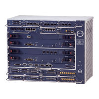
ECI X36419 Installation And Maintenance Manual (266 pages)
Brand:
ECI
| Category:
Storage
| Size: 14.13 MB
Table of Contents
Table of Contents
3
About this Manual
14
Document Organization
14
Document Conventions
14
Related Documentation
15
Obtaining Technical Documentation
15
Technical Assistance
16
Introduction
17
XDM-300 Platform Overview
17
XDM-300 I/O Protection Options
18
Figure 1-1: XDM-300 Shelf
18
Figure 1-2: Basic XDM-300 Shelf, Horizontal Installation
19
Figure 1-3: Basic XDM-300 Shelf, Vertical Installation
20
Figure 1-4: XDM-300 with One TPU on Top of the Shelf
21
Figure 1-5: XDM-300 with Two Tpus
22
Shelf with CWDM Networking Capabilities
23
Figure 1-6: XDM-300 with an OCU and Two Tpus
23
Before You Start
25
Overview
25
Outline of Installation Procedure
25
Site Preparation
28
Table 2-1: Equipment Dimensions
29
Tools and Test Equipment
30
Table 2-2: Recommended Coaxial Cable Assembly Tools
30
Installing the XDM-300 in Racks
31
Figure 2-1: ETSI a Rack Closed View
33
Figure 2-2: XDM-300 - Typical Horizontal Installation in an ETSI a Rack
35
Figure 2-3: Typical Installation of XDM-300 and XDM-100 Shelves in an ETSI a Rack
36
Figure 2-4: Typical Installation of XDM-300 and XDM-1000 Shelves in an ETSI a Rack
37
Preparing Cables and Fibers
38
Table 2-3: Traffic Cables Mating Connector Data
41
Table 2-4: Patch Traffic Cables Connecting I/O Modules to the TPU
42
Table 2-5: Optical Fibers and Mating Connector Data
43
Work and Equipment Safety
44
Figure 2-5: Grounding Connections at Typical Site
45
Figure 2-6: XDM-300 Grounding Posts
47
Figure 2-7: XDM-300 CE Label
48
Table 2-6: 2.5 Gbps Optical SFP Transceivers for Transponders/Combiners
51
Table 2-7: Gbe/Fc/Ficon SFP Optical Transceivers for Transponders/Combiners
51
Data Cables for Eismbs, Dioms, and Mcsms
52
Table 2-8: EISMB Optical Fibers and Mating Connector Data
52
Table 2-9: EISMB Ethernet Electrical Cables and Mating Connector Data
52
Table 2-10: DIOM Optical Fibers and Mating Connector Data
53
Table 2-11: DIOM Ethernet Electrical Cables and Mating Connector Data
53
Table 2-12: MCSM Optical Fibers and Mating Connector Data
53
Protection against ESD
54
Figure 2-8: Basic ESD Warning Symbol
54
Table 2-13: MCSM Ethernet Electrical Cables and Mating Connector Data
54
Figure 2-9: XDM-300 Typical Temporary EPA Arrangement
57
Equipment Installation
59
Overview
59
Figure 3-1: Components of Horizontal XDM-300 Installation
61
Table 3-1: Outline of Horizontal XDM-300 Installation Sequence
62
Figure 3-2: Components of XDM-300 Vertical Installation
64
Table 3-2: Outline of Vertical XDM-300 Installation Sequence
65
Unpacking and Performing Visual Inspection
67
Installation Options
68
Figure 3-3: XDM-300 - Typical Horizontal Installation in an ETSI a Rack
69
Figure 3-4: Typical Horizontal Installation of Two XDM-300 Shelves in an ETSI a Rack
70
Figure 3-5: Typical Horizontal Installation of Three Basic XDM-300 Shelves in 2200 MM ETSI a Rack
71
Figure 3-6: Typical Horizontal Installation of Three XDM-300 Shelves with Tpus in 2600 MM ETSI a Racks
72
Figure 3-7: XDM-300 - Typical Vertical Installation in an ETSI a Rack
73
Installing Ancillary Units in Racks
74
Figure 3-8: Location of Xrap-B Grounding Stud
77
Figure 3-9: Identification of Xrap-B Cable Routes
77
Figure 3-10: Connecting DC Power Cables to the Xrap-B
78
Figure 3-11: Identification of Xrap-B Connectors
79
Figure 3-12: Installation of Xrap-B Circuit Breakers
80
Table 3-3: XDM-300 Recommended Circuit Breakers
81
Figure 3-14: Identification of Xrap-100 Cable Routes
85
Figure 3-15: Connecting DC Power Cables to the Xrap-100
85
Figure 3-16: Identification of Xrap-100 Connectors
86
Figure 3-17: Installation of Xrap-100 Circuit Breakers
88
Table 3-4: XDM-300 Recommended Circuit Breakers
89
Figure 3-18: Cable Guide
90
Figure 3-19: Fiber Guide for ETSI a Racks
91
Figure 3-20: Cable Slack Tray
91
Figure 3-21: Threading Optical Fibers in the FST
92
Figure 3-22: Attaching Rack Mount Brackets to the ODF
94
Figure 3-23: ODF Front Panel
94
Figure 3-26: Threading and Connecting Optical Fibers in the OPP
98
Installing the Shelf in the Rack
99
Figure 3-27: Installing the Vertical Lower Bracket
101
Figure 3-28: Preparing the Filter Frame Assembly
102
Figure 3-29: Installing the Filter Frame Assembly
103
Figure 3-30: Installing the Vertical Upper Bracket
104
Figure 3-31: Installing the Thumbnuts
105
Figure 3-32: Releasing the Thumbnuts
106
Figure 3-33: Lowering the Filter Frame
107
Figure 3-34: Filter Frame in Lower Position
108
Figure 3-35: Inserting the Air Filter
109
Grounding the XDM-300 Shelf
110
Figure 3-36: XDM-300 Shelf and Rack Grounding
110
Installing XDM-300 Cards
111
Figure 3-37: Installing the FCU300
112
Figure 3-38: Installing the ECU300/ECU300-F
113
Figure 3-39: Installing the MXC300
114
Figure 3-40: Installing the NVM in the MXC300
115
Figure 3-41: Installing a Quad I/O Card
117
Installing XDM-300 Modules
118
Figure 3-42: Inserting an I/O Module in the I/O Slots
120
Figure 3-43: Installing the SIM16_1 Mechanical Adapter
121
Figure 3-44: Inserting an SFP/XFP Transceiver into an I/O Module
124
Figure 3-45: Installation of Typical Double-Slot Modules in the XDM-300
125
Figure 3-46: Removing the Module Guide
126
Installing TPU Modules
127
Figure 3-47: Inserting the TC Module (XDM-300)
128
Figure 3-48: Inserting a Single-Slot TPM in the TPU (XDM-300)
129
Figure 3-49: Inserting a Double-Slot TPM in the TPU (XDM-300)
131
Figure 3-50: Removing a TPM Guide
132
Figure 3-51: Inserting a Triple-Slot TPM in the TPU (XDM-300)
133
XDM-300 Accessories
135
Figure 3-52: Xrap-B Front Panel
136
Table 3-5: Xrap-B Front Panel Component Functions
136
Figure 3-53: Xrap-B Connectors
137
Table 3-6: Xrap-B Connector Functions
138
Figure 3-54: Xrap-100 Front Panel
139
Table 3-7: Xrap-100 Front Panel Component Functions
139
Figure 3-55: Xrap-100 Connectors
140
Table 3-8: Xrap-100 Connector Functions
141
Table 3-9: RAP Features
142
Connecting Fibers and Cables in ETSI a Racks
143
Figure 3-56: Routing Cables and Fibers in an ETSI a Rack
143
Table 3-10: XDM-300 Protection Schemes
151
Figure 3-57: XDM-300 1:1 Protection Scheme Example
152
Table 3-11: XDM-300 1:1 I/O Protection
152
Figure 3-58: XDM-300 1:2 Protection Scheme Example
153
Table 3-12: XDM-300 1:2 I/O Protection
153
Figure 3-59: XDM-300 1:3 Protection Scheme Example
154
Table 3-13: XDM-300 1:3 I/O Protection
154
Figure 3-60: XDM-300 1:3 Protection Scheme Example
155
Figure 3-61: Connecting to a TPMH_1 Protection with an XDM-300
156
Figure 3-62: XDM-300 with 252 E1S in 1:2 Protection Connections
157
Figure 3-63: RJ-45 Extractor
162
Figure 3-64: Inserting the Cables (Upper Row)
162
Figure 3-65: Attaching the Extractor to the Handle (Upper Row)
163
Figure 3-66: Extracting the Connector (Upper Row)
163
Figure 3-67: LC/SFP Extractor
164
Figure 3-68: Inserting the Cables (Lower Row)
164
Figure 3-69: Attaching the Extractor to the Handle (Lower Row)
165
Figure 3-70: Extracting the Connector (Lower Row)
165
Figure 3-71: Inserting the Fiber into the Extractor
166
Figure 3-72: Pressing Extractor's Release Tab Onto Sfp's Clip
166
Figure 3-73: Extracting the LC Connector
167
Figure 3-74: Moving the Connector Beyond the Tab
167
Figure 3-75: Removing the Fiber
167
Figure 3-76: Inserting the Fiber into Extractor's Narrow End
168
Figure 3-77: Moving Extractor's End to the Connector
168
Figure 3-78: Inserting the Connector into the SFP
168
Figure 3-79: Moving the Extractor Backward
169
Figure 3-80: Removing the Extractor from the Fiber
169
Figure 3-81: Orienting the Extractor in Front of the SFP
169
Figure 3-82: Moving the Extractor Forward
170
Figure 3-83: Fitting Sfp's Partition into Extractor's Slot
170
Figure 3-84: Moving Extractor Toward SFP Clip
170
Figure 3-85: Pulling the Extractor Backward with Grasped Clip
171
Figure 3-86: Locking the Clip between Lever and Extractor's Teeth
171
Figure 3-87: Releasing the SFP from Housing
171
Figure 3-88: Extracting the SFP
172
Figure 3-89: DIN 1.0/2.3 Extractor
173
Figure 3-90: Placing the Extractor in Front of the Connector
174
Figure 3-91: Attaching the Extractor to the Connector's Step
174
Figure 3-92: Extracting the Connector
175
Maintenance
191
Overview
191
Required Test Equipment, Tools, and Materials
191
Preventive Maintenance
192
Table 4-1: Preventive Maintenance Inspection and Checks
192
Traffic Monitoring System
197
Table 4-2: I/O Modules Monitoring Data
200
Onsite Troubleshooting
202
Table 4-3: Troubleshooting Power Problems
203
Table 4-4: General Troubleshooting Procedures for Cards/Modules
204
Table 4-5: General Troubleshooting Procedures for Optical Transceiver Plug-Ins
205
Table 4-6: Troubleshooting Procedures for Electrical Interface Modules
205
Table 4-7: Troubleshooting Procedures for Optical OADM and Mux/Demux
206
Table 4-8: Troubleshooting Procedures for Eisms
206
Table 4-9: Troubleshooting Procedures for Timing Subsystem
207
Table 4-10: Troubleshooting Transmission and Traffic Alarms
208
Table 4-11: Troubleshooting Management Communication
209
Replacing Cards and Modules
210
Replacing RAP Components
218
Connectors Pin Assignment
222
ECU300/ECU300-F Card Connectors
222
Table A-1: ALARMS Connector Pin Assignment
223
Table A-2: ALARMS Client Cable Wiring
224
Table A-3: Xrap-100 Alarms Cable Wiring
225
Table A-4: F-CHANNEL Connector Pin Assignment
227
Table A-5: T3_1/T4_1 and T3_2/T4_2 Connectors Pin Assignment
228
Table A-6: ETHERNET Connectors Pin Assignment
229
MXC300 DC Input Power Connectors
230
Table A-7: PIM2_21 Receive Lines (Upper) Connector Pin Assignment
231
Table A-8: PIM2_21 Transmit Lines (Lower) Connector Pin Assignment
232
PIM2_63/B Connection Data
234
Table A-9: PIM2_63/B Typical Receive Lines (Upper) Connector Pin Assignment
234
Table A-10: PIM2_63 Typical Transmit Lines (Lower) Connector Pin Assignment
236
EISMB/DIOM/MCSM Connectors
237
Table A-11: 10/100Baset Connectors Pin Assignment
238
Table A-12: 1000Baset Connector Pin Assignment
238
Xrap-100 Connectors
239
Table A-13: SHELF Alarm Connectors Pin Assignment
240
Table A-14: ALARM IN/OUT Connector Pin Assignment
242
Xrap-B Connectors
245
Table A-15: SHELF Alarm Connectors Pin Assignment
246
Table A-16: ALARMS Connector Pin Assignment
248
Rack Installation
253
Installing Equipment Racks
253
19" Rack Installation
258
Reference Documents
259
Index
265
Advertisement
Advertisement
Related Products
ECI XDM-300
ECI Categories
Storage
Network Hardware
Motherboard
Light Fixture
Control Panel
More ECI Manuals
Login
Sign In
OR
Sign in with Facebook
Sign in with Google
Upload manual
Upload from disk
Upload from URL