Sign In
Upload
Manuals
Brands
Eaton Manuals
Security System
RTK 725B range
Eaton RTK 725B range Manuals
Manuals and User Guides for Eaton RTK 725B range. We have
1
Eaton RTK 725B range manual available for free PDF download: Instruction Manual
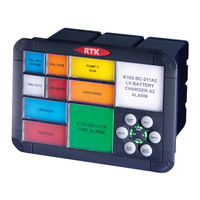
Eaton RTK 725B range Instruction Manual (120 pages)
Alarm annunciator
Brand:
Eaton
| Category:
Security System
| Size: 12.59 MB
Table of Contents
Table of Contents
3
1 Introduction
7
General
7
Programmable Features
7
Glossary of Terms
8
Annunciator Model Code Definition
9
Product Overview
11
System Front View
11
Number of Alarms Per Cell
12
Integral Pushbutton Location
12
Window Illumination
12
LED Failure Indication
13
Window Colours
14
Adding or Changing Film Legends
14
Filter & Bezel Spare Parts Numbers
15
Laser Printed Legends
15
Window Numbering System
15
Integral Pushbutton Module
16
Pushbuttons
16
Watchdog Monitoring Led's
16
USB Programming Port
17
CAL Mode
18
Signal Input Contact Status
19
Configuring Alarm Inputs for Use with N/O or N/C Field Contacts
19
Function up / down
20
Channel up / down
20
Remote Pushbutton Module
21
Audible Alarms
21
2 Cell Types
22
A Cell Detail (Alarm Cell)
22
A Cell - Differential Input Version
23
AR Cell Detail (Alarm - Relay Cell)
24
AR Cell - Differential Input Version
25
AP Cell Detail (Alarm - Pushbutton Cell)
26
APR Cell Detail (Alarm / Pushbutton - Relay Cell)
27
AP6 Cell Detail (Alarm Card - Remote Pushbutton)
28
AWR Cell Detail (Alarm - Watchdog Relay Cell)
29
AS Cell Detail (Alarm - Supply Cell)
30
AS Cell - Differential Input Version
31
S Cell Detail (Supply Cell)
32
SS Cell Detail (Supply - Supply Cell)
33
WR Cell Detail (Watchdog - Relay Cell)
34
WRS Cell Detail (Watchdog / Relay - Supply Cell)
35
WRR Cell Detail (Watchdog / Relay - Relay Cell)
36
Optional WR Cell Detail (Watchdog - Relay Cell)
37
WRP Cell Detail (Watchdog Relay Card - Remote Pushbutton)
38
AC Cell Detail (Alarm - Comms Cell)
39
APC Cell Detail (Alarm - Pushbutton - Comm's Cell)
40
C Cell Detail (Comm's Cell)
41
WRC Cell Detail (Watchdog / Relay - Comm's Cell)
42
CE Cell Detail (Comms Enhanced Cell)
43
ACE Cell Detail (Alarm - Comm's Enhanced Cell)
44
WRCE Cell Detail (Watchdog / Relay - Comm's Enhanced Cell)
45
CEC Cell Detail (Comm's Enhanced - Comm's Cell)
46
PCE Cell Detail (Remote Pushbutton - Comm's Cell)
47
3 Logic Supply & Fusing
48
Externally Powered Systems
48
SI/O Card Versions
48
Systems Using Internal Power Cards
49
SI/O Card Versions
49
4 Power Supply Monitoring
50
Power Monitor Relays
50
Power Monitor Led's
50
5 Signal Voltage Setting / Wiring
51
Setting Inputs for Use with 24VDC or 125VDC
51
Setting Inputs for Use with 24VAC or 125VAC
51
Setting Inputs for Use with 48VDC
52
Setting Inputs for Use with 48VAC
52
Standard 24VDC Signal Input Wiring
53
Optional 24VDC Powered Input Wiring
54
Optional 24VAC Signal Input Wiring
55
Optional 125VDC Signal Input Wiring
56
Optional 125VAC Signal Input Wiring
57
Optional 48VDC Signal Input Wiring
58
Optional 48VAC Signal Input Wiring
59
Optional Differential Input Version Wiring
60
6 Common Relays
61
Group Relay
62
Group Relay with Reflash
62
Pushbutton Follower Relay
62
Diagnostic / Watchdog Relay
62
All Faults Monitoring
62
Field Contact Monitoring
62
System Fault Monitoring
63
Communication Failure Monitoring
63
Power Failure Monitoring
63
Card Fault Monitoring
63
Ground Fault Monitoring
63
LED Failure Monitoring
63
GPS Monitoring
63
Printer Fault Monitoring
63
Real Time Clock Fault Monitoring
63
7 Individual Channel Repeat Relays
64
Input Follower
64
Logic Follower
64
Display Follower
64
Cancel System Test Relay
65
Typical RTK 725B Rear Views
66
Typical Large Window Version
66
Typical Medium Window Version
67
Typical Small Window Version
68
8 Installation
69
Unpacking
69
Basic Principles of Handling
69
Mounting
70
Panel Mouting
70
19" Rack Mounting
71
Wall Mounting
71
Floor Mounting
71
9 Specifications
72
Outputs
73
Individual Channel Repeat Relays
73
Common Relays
73
Audible Alarms
73
Communications
73
Environmental Specifications
74
10 Spare Parts List
75
11 Servicing
78
Module Removal
78
Card Address Setting
80
Small Window Versions
81
Medium Window Versions
82
Large Window Versions
83
Typical Alarm Card DIL Switch SW1 Address Settings
84
12 Contact / Returns
85
13 Communications Options
86
Entry Level Versions
86
Standard Comms Version
87
Enhanced Comm's Version
89
Protocols
90
Modbus
90
Modbus Slave - Entry Level
92
Read Coil Status - Function 01 - Response
92
Write Multiple Coils - Function 15 - Request
93
Write Multiple Coils - Function 15 - Response
94
Modbus Slave - Standard Communications
95
Read Coil Status - Function 01 - Request
95
Read Coil Status - Function 01 - Response
95
Read Status - Function 03 - Request
96
Read Status - Function 03 - Response
97
Write Single Register - Function 6 - Request
99
Write Single Register - Function 6 - Response
100
Write Multiple Coils - Function 15 - Request
101
Write Multiple Coils - Function 15 - Response
101
Write Multiple Registers - Function 16 - Request
102
Write Multiple Registers - Function 16 - Response
103
Modbus Master - Standard Communications
104
Read Status - Function 03 - Request
105
Read Status - Function 03 - Response
105
Rtk Ams
106
Wharton Format
106
Mapping
106
IEC61850 Server
113
SNTP Client
115
14 Standard Comms Card Detail
116
Real Time Clock
117
15 Enhanced Comms Card Details
118
Real Time Clock
118
16 Safety
119
Advertisement
Advertisement
Related Products
Eaton RTK UC625
Eaton RTLOC-18909A-T2
Eaton RTC-100
Eaton Fuller RTLO-14610B
Eaton Fuller RTLOF-12610B-T2
Eaton RT-11109A-AT
Eaton RTO-9109A-AT
Eaton RTO-14109B-ATS
Eaton RTO-13109B-ATE
Eaton RT-11109A-ATR
Eaton Categories
UPS
Circuit breakers
Industrial Equipment
Switch
Industrial Electrical
More Eaton Manuals
Login
Sign In
OR
Sign in with Facebook
Sign in with Google
Upload manual
Upload from disk
Upload from URL