Sign In
Upload
Manuals
Brands
Eaton Manuals
Circuit breakers
NZM3
Eaton NZM3 Manuals
Manuals and User Guides for Eaton NZM3. We have
1
Eaton NZM3 manual available for free PDF download: Manual
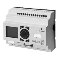
Eaton NZM3 Manual (208 pages)
Circuit-Breaker Communication System
Brand:
Eaton
| Category:
Circuit breakers
| Size: 1.3 MB
Table of Contents
Before Commencing the Installation
4
Table of Contents
6
1 User Notes
10
Target Group
10
Proper Use
10
Improper Use
11
Modification Index
11
Writing Conventions
13
Writing Conventions
14
Device Designation
15
System Overview
15
2 DMI
16
System Concept
16
Device Overview
17
Setup of the DMI
17
DMI System
18
Keypad
18
Operating Principle
18
Menu Structure
19
Main Menu
19
Special Menu
21
Engineering and Installation
21
Mounting
22
Mounting on a Top-Hat Rail
23
Connecting Fieldbus Modules
23
Connection Terminals
25
Installation Regulations, EMC
25
Connecting the Power Supply
26
Cable Protection
26
Connecting Inputs
27
Connecting the Inputs on the DMI
27
Connecting Outputs
28
Connecting the Outputs on the DMI
28
Connecting Circuit-Breakers
29
Commissioning
31
Switching on
31
Setting the Menu Language
32
Data Interrogation
33
Display Menu
33
Menu Overview
34
Parameters
36
Currents
36
I/O Status
36
Motor Start
37
Time
37
Represent
38
Incorporating Values in the Standard Display
38
The Standard Display
38
Operating Principle of the Standard Display
39
Parameter Setting
40
Input Menu
40
Password Setting/Changing
40
Commands
46
Remote Operator
46
Q Assignment
46
Motor Starter
49
Function
50
Direct-On-Line Starter
50
Reversing Starter
51
Star-Delta Starter
52
Reversing Star-Delta Starter
53
Fieldbus Coupling
54
Contact Elements
59
Changeover Time
59
Com
59
Startup Behaviour
62
Set Clock
63
Diagnostics
64
NZM Status
64
Alarm
66
NZM Info
66
NZM Mode
66
DMI Status
67
Diagnostics
67
SW Version
67
Diagnostics 0 to 9
69
Current Parameters
70
Operating Hours
70
Switching Operations
70
Alarm Messages
71
Connection to Bus Systems
72
What to Do if
72
Technical Data
73
General
73
Ambient Conditions
74
Power Supply
76
Digital Inputs (24 V DC)
76
Digital Outputs (Relays)
77
3 Nzm-XDMI-Dpv1
80
Interface for DMI)
80
System Overview
80
Layout of the Device
82
Operating System Requirements
82
PROFIBUS Certification
82
Scope of Functions
82
Installation
83
Connect the Power Supply
83
Connecting the PROFIBUS-DP
84
PROFIBUS-DP Connection Assignment
84
Bus Terminator
85
Potential Isolation
85
Baud Rates
85
Maximum Distances / Bus Cable Lengths
86
Cable Lengths
86
Operating the Device
86
Putting the PROFIBUS-DPV1 Interface into Operation
86
LED Status Displays
87
POW LED, Function
87
BUS LED, Function
88
Commissioning the PROFIBUS-DP Line with NZM-XDMI-DPV1
88
GSD File
88
Configuration of the Class 1 DP Master
89
Cyclic Data Exchange with Class 1 DP Master
90
PROFIBUS-DPV0 Functions
90
Format of the Data Inputs
91
Data Content of Module 1 Data Inputs
94
Meaning of the Data Inputs
94
Format of the Data Outputs
95
Meaning of the Data Outputs
96
Address Assignment of the Module 2 Data Inputs
97
Format and Meaning of the Data Outputs
100
Address Assignment of the Module 3 Data Inputs
101
Diagnosis with Class 1 DP Master
111
Format of the Diagnosis Information
111
Address Assignment of the Diagnosis Information
112
Data Content of the Diagnosis Information
114
Meaning of the Diagnosis Information
114
PROFIBUS-DPV1 Functions
118
Function Overview
118
Process Data Objects in NZM-XDMI-DPV1
120
Object Overview
120
Access to Objects
122
Process Data Objects
123
Intended Usage
124
Addressing and Length of the Object
124
Variable Definitions (Example) for the Object
125
Format and Meaning of the Object Data Content
125
Circuit-Breaker Parameters Used Object
139
Circuit-Breaker Device Identification Object
147
Circuit-Breaker/DMI Command Object
150
Circuit-Breaker/DMI Communication Status Object
155
DMI Output Assignment Object
157
Assignment of the Outputs with Motor-Starter Functions
162
Motor-Starter Function and Its Values
162
Assignment of the Outputs with Remote Operator Functions
163
Display of Used Parameters
166
Display of Actual Current Values
167
DMI Basic Settings Object
167
Display of the Current State of the Inputs/Outputs
167
DMI Clock Object
171
Menu Languages and Their Values
171
NZM-XDMI-DPV1 Device Identification Object
181
Circuit-Breaker/DMI Statistic Values Object
182
Object Compilation B
190
DPV1 Error Messages
195
Index
202
Advertisement
Advertisement
Related Products
Eaton NZMB Series
Eaton NZMN Series
Eaton NZM2
Eaton NZM1-XFIR Series
Eaton NZM1-4-XFI300R
Eaton NZM1-XFIU
Eaton NZM1 XFI U Series
Eaton NZM1-XFI300U
Eaton NZM1-4-XFI30U
Eaton NZM1-4-XFI300U
Eaton Categories
UPS
Circuit breakers
Industrial Equipment
Switch
Industrial Electrical
More Eaton Manuals
Login
Sign In
OR
Sign in with Facebook
Sign in with Google
Upload manual
Upload from disk
Upload from URL