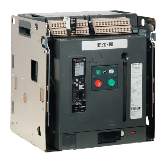
Sign In
Upload
Manuals
Brands
Eaton Manuals
Control Unit
NRX Digitrip 1150
Eaton NRX Digitrip 1150 Manuals
Manuals and User Guides for Eaton NRX Digitrip 1150. We have
1
Eaton NRX Digitrip 1150 manual available for free PDF download: Instruction Leaflet
Eaton NRX Digitrip 1150 Instruction Leaflet (98 pages)
Trip Units
Brand:
Eaton
| Category:
Control Unit
| Size: 56.05 MB
Table of Contents
Table of Contents
2
Section 1: Introduction
5
Figure 1. Digitrip 1150 Trip Unit with Rating Plug and Frame Module
5
Figure 2. NRX NF Circuit Breaker with Digitrip 1150
5
Section 2: Specification Tables
6
Section 3: General Description
13
Figure 3. Series NRX NF Frame Phase Current Sensor
13
Figure 4. Trip Unit Installation on a Frame Module
14
Figure 5. Installation of the Rating Plug into the Trip Unit
14
Figure 6. Trip Unit Locking Tabs
15
Figure 7. Frame Module with Trip Unit Removed
15
Section 4: Principles of Operation
16
Figure 8. Block Diagram with Breaker Interface
16
Figure 9. Series NRX RF Frame Neutral Sensor
18
Figure 10. Series NRX NF Frame Neutral Sensor
18
Section 5: Display Module Interface
20
Figure 11. Trip Unit and Display Module
20
Figure 12. Trip Unit Indicators (LSIG Style with Maintenance Mode)
20
Figure 13. Display Module Push Buttons
21
Section 6: Programming Settings
24
Figure 14. Long Delay Time Setting Bands for I T Settings
24
Figure 15. Short Delay Time Setting Bands - Flat and I 2 T
25
Section 7: Test Procedures
28
Figure 16. Functional Test Kit
28
Figure 17. Connections for Single-Pole, Single-Phase Current Tests
30
Figure 18. Connections for Single-Phase Current Tests with Two Poles in Series
30
Section 8: Record Keeping
31
Figure 19. Typical Trip Function Record Nameplate
31
Figure 20. Automatic Trip Operation Record
31
Figure 21. Typical Performance Test Record Form
32
Section 9: Trip Unit Battery
33
Figure 22. Digitrip Battery Installation
33
Section 10: Frame Ratings and Rating Plugs
34
Section 11: Maintenance Mode Feature
35
Section 12: References
36
Section 13: Time-Current Curves
36
Section 14: Communications
37
Figure 23. CAM Module
37
Appendix A: Zone Selective Interlocking Examples
38
Figure 24. Example of Interlocking with Three Zones
39
Figure 25. ZSI Example with Mains (M1, M2) and Tie (T) Circuit Breakers
39
Appendix B: Troubleshooting
40
Appendix C: Electrical Specifications
42
Appendix D: Display, Indicators and Menus
43
Appendix E: Power and Power Factor Sign Conventions
92
Figure 26. IEC Sign Convention Phasor Diagram
92
Figure 27. IEEE Sign Convention Phasor Diagram
93
Figure 28. IEEE Direct Mathematical Sign Convention Phasor Diagram
93
Appendix F: Setpoint Defaults and Worksheet
94
Advertisement
Advertisement
Related Products
Eaton NRX Digitrip Series
Eaton NH00
Eaton NH1
Eaton NH2
Eaton NZM XMC Series
Eaton NZM3-4-XMC-S0
Eaton NZM2-XMC-MB-250
Eaton NZM-XMC-KIT-630
Eaton NZM3-4-XMC-MB
Eaton NZM3-XMC-MB
Eaton Categories
UPS
Circuit breakers
Industrial Equipment
Switch
Industrial Electrical
More Eaton Manuals
Login
Sign In
OR
Sign in with Facebook
Sign in with Google
Upload manual
Upload from disk
Upload from URL