Sign In
Upload
Manuals
Brands
Eaton Manuals
Industrial Equipment
Magnefix MF 15 kV
Eaton Magnefix MF 15 kV Manuals
Manuals and User Guides for Eaton Magnefix MF 15 kV. We have
1
Eaton Magnefix MF 15 kV manual available for free PDF download: User Manual
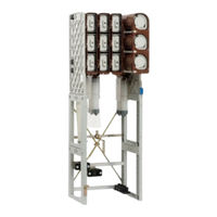
Eaton Magnefix MF 15 kV User Manual (183 pages)
MV switchgear
Brand:
Eaton
| Category:
Industrial Equipment
| Size: 9 MB
Table of Contents
Table of Contents
3
Introduction
7
General System Description
7
Using the Manual
7
Target Group
7
Structure of this Manual
7
Safety Instructions
8
General Regulations
8
Safety of the Operating Area
8
Notation Guide
9
What to Do in the Event of a Fire
9
Product Information
9
Type Plate
9
System Description
11
The Switchgear
11
Type of Switchgear
11
Configuration of Switchgear
11
Cable Panel
11
The Branch-Circuit Panel
11
The Fuse Panel
12
The Busbar Connecting Panel
12
Switching on and off
12
The Overcurrent Indicator
13
Earthing
13
Equipment Safety
13
Safe Operation
13
Safety Measures
14
Use of Safety Features
14
Execution of Work
14
Safety Markings
14
General Technical Data
15
Electrical Data
15
Dimensions and Weights
16
Heat, Radiation, Noise and Gases
18
System Assembly
19
Environmental Requirements
19
General
19
During Operation
19
Ventilation
20
Transportation and Storage
20
Floor
21
Ceiling
21
Assembling the Upright Frame
22
Parts List for Upright Frame
22
Assembling the Frame Legs
22
Fixing the Front C-Section
23
Fixing the C-Sections to the Frame
23
Fixing the Earth Bar to the Frame
23
Fitting the Cross Coupling
24
Fixing the Second Frame Leg
24
Fitting the Earth Strip
24
Positioning the Switchgear on the Frame
25
Check
25
Spare Panels
25
Assembling the Wall Frame
26
Parts List for Wall Frame
26
Fixing the Front C-Sections
27
Fixing the C-Sections to the Frame
27
Fixing the Earth Bar
27
Preparing the Fixed Section
28
Fixing the Frame
28
Fixing the Installation to the Wall
28
Fixing the Earth Strip
29
Check
29
Spare Panels
29
Extension of the Magnefix
30
Preparations
30
Wall Frame/Upright Frame
30
Support
31
Special Tools
31
Required Materials (Upright Frame)
32
Required Materials (Wall Frame)
32
Extension with a Transformer Panel
33
To a Transformer Panel on the Right-Hand Side
33
To a Transformer Panel on the Left-Hand Side
42
To a Cable Panel on the Right-Hand Side
51
To a Cable Panel on the Left-Hand Side
60
Extension with a Cable Panel
70
To a Transformer Panel on the Right-Hand Side
70
To a Transformer Panel on the Left-Hand Side
80
To a Cable Panel on the Right-Hand Side
90
To a Cable Panel on the Left-Hand Side
99
Connecting the Cables, General
108
Cable Connection Points
108
Fixing the Cables
108
Fixing the Cable Cores
109
Cable Boxes for Paper-Insulated Lead-Covered Cables
109
Cable Boxes for Plastic-Insulated Cables
111
Cable Boxes to Deviating Specification
111
Connecting the Paper-Insulated Lead-Covered Cables
112
Connection of Paper-Insulated, Lead-Covered Cu Cables up to 3 X 95 MM , Universal Clamps
112
Connection of Paper-Insulated, Lead-Covered Cables 3 X 120 MM
116
Clamps
116
And 3 X 150 MM
116
Gland
121
Bushing
124
With Plastic Entry
124
Filling the Cable Boxes
128
Required Materials
128
Procedure
128
Connection of Plastic-Insulated Cables
132
Connection of Plastic Insulated Cu Cables up to 3 X 70 MM , Universal Clamps
132
Plastic-Insulated Cables with Copper Cores Ranging from 3 X 95 MM
135
Clamps
135
To 3 X 240 MM
135
Plastic-Insulated Cable in a Top Connection
139
Connecting a Cable Using Alternative Materials
140
Connection of Eaton 16 MM Transformer Cable to the Protected Branch
141
Connection of Other Cables to the Protected Branch of the Universal Clamps
144
System Operation
146
Safe Switching
146
Safe Switching-On
146
Safe Switching-Off
146
Switching
146
Switching-On
147
Switching-Off
149
Changing a Fuse
150
Resetting an Overcurrent Indicator
152
Electromechanical Overcurrent Indicator
152
Electronic Overcurrent Indicator
152
Voltage Indication
153
Voltage Indication
154
System 'DEAD' Indication
154
Phase Coincidence Indication
155
Proving Phase Coincidence
156
Earthing
157
Equipment
157
Single-Pole Earthing
158
Fitting Three-Pole Quick Earthing
160
Removing Three-Pole Quick Earthing
162
Earthing a Transformer
163
Measuring and Testing
164
Measuring and Testing Without Measuring Rods
164
Measuring and Testing Using the Measuring Rods
164
System Commisioning and Decommisioning
166
Commissioning
166
Acceptance Testing
166
Inspection
166
Acceptance
166
Decommissioning
166
Dismantling
166
Procedure
167
Disposal
167
Testing the Extension
168
Preparations
168
Mechanical Testing
168
Voltage Drop Measurements
169
High Voltage Test
173
System Inspection, Maintenance and Repair
174
Logbook
174
Inspection and Maintenance
174
Types of Maintenance
174
Frequency
174
Tools
175
Cleaning
175
Switchgear Has Been Made Dead
175
Inspection and Maintenance Schedule
176
Periodic Checks
176
Service Overhaul
176
Locating a Malfunction
176
What to Do in the Event of a Fault
176
Accessories
177
Spare Parts
177
Accessories
182
Glossary
183
Personnel and Authorities
183
Abnormal Operating Conditions
183
Equipment and Its Environment
183
Advertisement
Advertisement
Related Products
Eaton Indoor MVS-ND
Eaton RMQ-Titan M22-K Series
Eaton RMQ-Titan M22-CKC Series
Eaton RMQ-Titan M22-K-SMC Series
Eaton RMQ-Titan M22-PVS MS Series
Eaton RMQ-Titan M22-XZK
Eaton RMQ-Titan M22-XAK
Eaton RMQ-Titan M22-PV60P
Eaton SONIX Ms12
Eaton RMQ-Titan M22S-PV Series
Eaton Categories
UPS
Circuit breakers
Switch
Industrial Equipment
Industrial Electrical
More Eaton Manuals
Login
Sign In
OR
Sign in with Facebook
Sign in with Google
Upload manual
Upload from disk
Upload from URL