Sign In
Upload
Manuals
Brands
EATON Manuals
Measuring Instruments
2075
EATON 2075 Manuals
Manuals and User Guides for EATON 2075. We have
2
EATON 2075 manuals available for free PDF download: Operation Manual
EATON 2075 Operation Manual (180 pages)
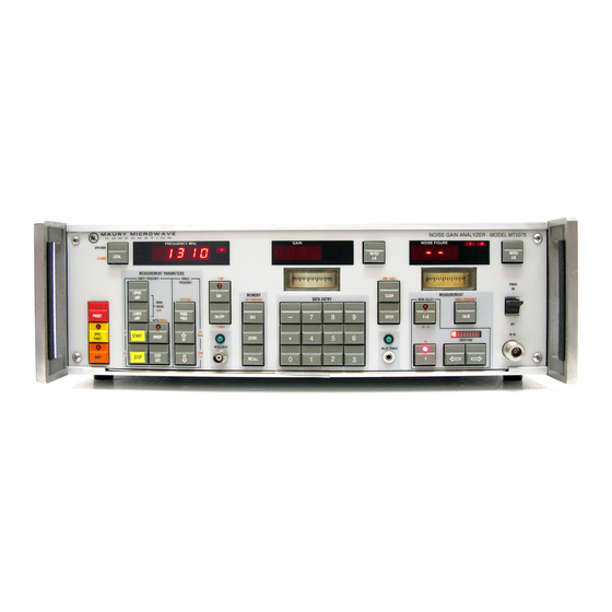
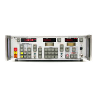
NOISE-GAIN ANALYZER
Brand:
EATON
| Category:
Measuring Instruments
| Size: 3.38 MB
Table of Contents
Table of Contents
3
Scope and Organization of the Manual
9
Eaton 2075 Noise Gain Analyzer
9
Section 1-General Information
9
Calibration Cycle
10
Introduction
10
Purpose and Use of Equipment
10
Selecting the Correct Test Configuration
10
Equipment Required but Not Supplied
11
Equipment Supplied
11
Optional Accessories
12
Specifications
13
Supplemental Specifications
15
Safety Precautions
16
Section 2- Installation
19
AC Power Requirements
19
AC Voltage Selection Card
20
Introduction
19
Unpacking and Physical Inspection
19
Operational Inspection
21
Operating Temperature
21
Selection of Relay DC Voltage
21
Equipment Mounting
23
Rack Mounting the Eaton 2075
23
Installation of Rack Mounts
23
Installation of Slide Mounts
24
Equipment Interconnections
25
GPIB Connector
25
GPIB Connector Pin-Out
26
Section 3 - Operation
27
Pre-Operational Adjustments
26
Reference Card
26
Capabilities of the Eaton 2075
27
Introduction
27
Controls and Indicators
29
Front Panel Controls and Indicators
33
Rear Panel Controls and Indicators
43
Power-On Conditions, Preset, and Total System Reset
44
Power-On, Preset, and Total System Reset Parameters
46
Special Functions
47
Continuous Measurement Mode and the Hold Function
48
Fixed Frequency Operation
49
Swept Frequency Operation
50
Uncorrected and Corrected Measurements
52
Uncorrected and Corrected Measurements
53
Entry of Frequency and ENR Values
54
Selecting the Correct Test Configuration
55
Test Configuration Downconversion Modes
58
Procedure for Test Configuration
59
3-5A Test Configuration 1- Calibration
59
Test Configuration 2- Measurement- Double Sideband
62
Test Configuration 2 Measurement (Single Sideband)
66
Test Configuration 3 Calibration
70
Test Configuration 3 Measurement
70
3-Lla Test Configuration 4- Calibration - Single Sideband
78
3-12A Test Configuration 5 -Calibration
82
Test Configuration 5 Measurement
82
Test Configuration 6 Calibration
86
Test Configuration 6 Measurement
87
Additional Types of Measurements
90
Operating Noise Temperature
92
Power (Db) Measurements
93
ENR Measurement
94
ENR Setup-Measurement
94
Manual Measurement of Noise Figure and Gain
95
Manual Measurements
95
Noise Measure (M) Measurement
95
Manual Measurement of Y-Factor
97
Manual Y-Factor Measurement
97
Calibrated Noise Source
98
Noise Drive Voltage and Indicator
99
Example of Calibrated Noise Source Data
99
ENR Tables
100
Enr Table 1, 2 or
101
Calibration
102
Frequency Calibration
102
Second Stage Calibration
103
Input Gain Selection
105
IF Attenuators Calibration
106
Selection of Sideband Parameters
106
Example 1 Sideband Selection
107
Example 2 Sideband Selection
108
Example 3 Sideband Selection
109
Example 4 Sideband Selection
110
Bandwidth Compensation
111
Bandwidth Compensation - Example 1
111
Determining the Bandwidth Ratio of the First and Second Stages
112
Bandwidth Compensation - Example 2
112
Insertion Loss Measurement with 2075
113
Insertion Loss Measurement with Power Meter
113
Compensation for Loss or Gain
114
Loss Compensation
115
Tcold Compensation
116
Error Caused by Tcold Deviation from 290 K
117
Oscilloscopes and Recorders to Display Data
117
Output Display Special Functions
118
Test Pattern 2 Oscilloscope Display
119
Noise Figure and Gain Oscilloscope Display
120
Controlling External Local Oscillators
123
Selecting an External Local Oscillator
123
Writing a Custom Program for Controlling a Local Oscillator
124
Special Functions
129
Error Messages
134
Smoothing Function
138
Store-Recall Registers
138
Smoothing Indicator
139
100 Khz Display Resolution
141
Software Revisions
141
Section 4-Gpib Operation
143
GPIB General Information
143
Introduction
143
General Purpose Interface Bus
144
GPIB Compatibility
145
GPIB Operating Modes
145
Setting the GPIB Address
145
GPIB Functional Capabilities
146
GPIB Message Types
146
Interface Bus Messages
146
Remote and Local Modes
146
GPIB Function Reference Table
148
Device Messages
150
Data Messages
154
Selection of Data Message Contents
154
Sample Data Output
156
Status Messages
158
Status Byte
159
Programming Example for Data Collection in Test Configuration 1 Using Srq on Data Ready with Hp85 Controller
161
Setup in Test Configuration 2
163
Flowchart for SRQ on Ready to Tune
165
Flowchart for SRQ on Data Ready
168
Sample Program
170
Section 5- Performance Verification Tests
173
Introduction
173
Test Equipment Required
173
Noise Drive Voltage Test
174
Performance Verification Procedures
174
Power-On Test
174
Final Detector Bias Test
175
IF Attenuators Calibration
175
Second Stage Calibration
176
Final Detector Linearity Test
177
Scope/Plotter Output Test
179
Output Test Pattern 2
180
Advertisement
Eaton 2075 Operation Manual (176 pages)
Brand:
Eaton
| Category:
Measuring Instruments
| Size: 11.92 MB
Table of Contents
Table of Contents
3
Section I -General Information
9
Scope and Organization of the Manual
9
Eaton 2075 Noise Gain Analyzer
9
Introduction
10
Purpose and Use of Equipment
10
Calibration Cycle
10
Selecting the Correct Test Configuration
10
Equipment Supplied
11
Equipment Required but Not Supplied
11
Optional Accessories
12
Specifications
13
Safety Precautions
16
Supplemental Specifications
16
Section 2 -Installation
19
Introduction
19
Unpacking and Physical Inspection
19
AC Power Requirements
19
AC Voltage Selection Card
20
Operational Inspection
21
Operating Temperature
21
Selection of Relay DC Voltage
21
External Relay Voltage Selection
22
Equipment Mounting
23
Rack Mounting the Eaton 2075
23
Installation of Rack Mounts
23
Installation of Slide Mounts
24
Equipment Interconnections
25
Reference Card
26
Pre-Operational Adjustments
26
Gplb Connector
26
Section 3 -Operation
27
Introduction
27
Capabilities of the Eaton 2075
27
Controls and Indicators
29
Front Panel Controls and Indicators
31
Rear Panel Controls and Indicators
41
Continuous Measurement Mode and the Hold Function
46
Fixed Frequency Operation
47
Swept Frequency Operation
48
Uncorrected and Corrected Measurements
50
Uncorrected and Corrected Measurements
51
Entry of Frequency and ENR Values
52
Selecting the Correct Test Configuration
53
Procedure for Test Config~~Ration I
54
Single Sideband
55
Test Configuration Downconversion Modes
56
Procedure for Test Configuration
57
Test Configuration 2 Calibration (Double Sideband)
60
Test Configuration 2 Measurement (Double Sideband)
60
Control Programs for External Local Oscillators
60
Test Configuration 4 Measurement Double Sideband
72
Single Sideband
79
Test Configuration 6 Measurement
85
Additional Types of Measurements
88
Example of Calibrated Noise Source Data
97
Bandwidth Compensation Example
110
Double Sideband
128
GPIB Function Reference Table
146
Special Functions
150
Selection of Data Message Contents
152
Advertisement
Related Products
Eaton 2000H(XL)
Eaton 20000HXL31
Eaton RT 2000VAH
Eaton 20 kW Air-cooled
Eaton Interceptor 200
Eaton Smart Home Controller 2.0
Eaton 200 A 15 kV class
Eaton 200 A 25 kV class
Eaton 2000H
Eaton Power Distribution Rack 208V
EATON Categories
UPS
Circuit breakers
Industrial Equipment
Switch
Industrial Electrical
More EATON Manuals
Login
Sign In
OR
Sign in with Facebook
Sign in with Google
Upload manual
Upload from disk
Upload from URL