Sign In
Upload
Manuals
Brands
Dycor Manuals
Monitor
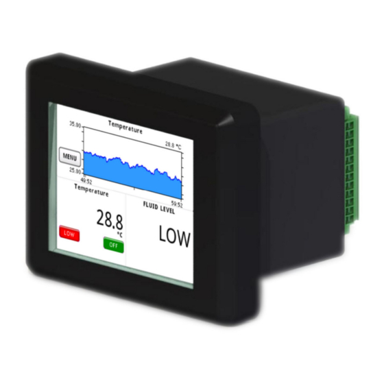
SmartVue Process Control Monitor
Dycor SmartVue Process Control Monitor Manuals
Manuals and User Guides for Dycor SmartVue Process Control Monitor. We have
1
Dycor SmartVue Process Control Monitor manual available for free PDF download: Operator's Manual
Dycor SmartVue Process Control Monitor Operator's Manual (138 pages)
Brand:
Dycor
| Category:
Monitor
| Size: 3 MB
Table of Contents
Proprietary Notice
2
Disclaimers/Warnings
3
Statement of Limited Warranty
4
Trademarks
4
FCC Notification
4
About this Manual
4
Table of Contents
5
Figures
8
Introduction
11
Getting Started
12
Connecting Power
12
Figure 2-1 External Power Connection
12
Starting up the Smartvue
13
Figure 2-2 Splash Screen
13
Figure 2-3 the Meter Screen
13
The Touch Screen Interface
14
Figure 2-4 the Various Keyboards for Text/Symbol Entry
14
Figure 2-5 Decimal and Hexadecimal Keypads
14
Table 2-1 Special Keyboard Keys
15
The Main Menu
16
Figure 2-6 the Main Menu Screen
16
Table 2-2 the Main Menu
16
Figure 2-7 Block Diagram of the Smartvue's Menus and Screens
18
Special Icons
19
I/O Configuration
20
Current Loop I/O
20
Figure 3-1 the Configure I/O Menu
20
Figure 3-2 the Current Loop I/O Configuration Menu
20
Figure 3-3 Configuration Screens for Current Loop I/O
21
Figure 3-4 J1 Wiring to Use Loop Powered Transmitter with Power from the Smartvue
21
Multipurpose I/O (Digital I/O and Voltage Inputs)
22
Figure 3-5 the Multipurpose I/O Configuration Menu
22
Total/Rate Counters
24
Figure 3-6 the Total/Rate Counters Configuration Menu
24
Temperature
25
Figure 3-7 the Configure I/O - Temperature Screen
25
Voltage Outputs
26
Frequency Outputs
26
Figure 3-8 the Configure I/O - 0-10V out 1 Screen
26
Figure 3-9 the Configure I/O - FREQ out 1 Screen
26
4-20Ma Calibration
27
Logic Thresholds
27
Setting up a Process
28
Figure 4-1 a Basic Process
28
Table 4-1 Smartvue Process Types
28
Figure 4-2 J2 Wiring for an RTD
31
Setting up a Control Process
33
Figure 5-1 Block Diagram of a Closed-Loop Control Process
33
Assigning and Configuring a Meter
37
Figure 6-1 Meter Screen Elements
37
Table 6-1 RTD Error Messages
41
Setting up an Output
42
Using the Current Loop Outputs
43
Figure 7-1 J1 Wiring to Use 4-20Ma out 1 in Active Mode
44
Figure 7-2 J1 Wiring to Use 4-20Ma out 1 in Passive Mode
44
Using the Analog Voltage Outputs
45
Using the Frequency Outputs
45
Figure 7-3 Voltage Device Connected to VOUT 1
45
Figure 7-4 Frequency Input Device Connected to FOUT 1
45
Using the Digital Outputs
46
Threshold Mode
46
Figure 7-5 Digital Output Configuration Screens
46
Latching Mode
47
Figure 7-6 Digital Output On/Off Behavior for Threshold Mode
47
Figure 7-7 Set Outputs Screens for Latching Mode with an Analog Input Source
47
Switching Mode
48
Figure 7-8 Pressing an Enabled Indicator Button on the Meter Screen Is a Convenient Way to Clear a Latch Condition
48
Figure 7-9 Set Outputs Screen for Latching Mode with a Digital Input Source
48
Figure 7-10 Set Outputs Screens for Switching Mode with a Digital Input Source
48
Fixed Outputs
49
Figure 7-11 Output Behavior for Normal and Inverted Polarities
49
Figure 7-12 J1 and J2 Wiring to Use 4-20Ma out 1 as External Setpoint Control Source
50
Run / Stop Modes
52
Figure 8-1 the Run / Stop Menu
52
Figure 8-2 the Meter Screen When the Stop Process Control Mode Is Engaged
52
Figure 8-3 the Meter Screen When the Disabled Configuration Mode Is Engaged
53
Ethernet Data Communications
54
Ethernet Settings
54
Figure 9-1 the Ethernet Settings Screen
55
Figure 9-2 Ethernet Services Menu
55
Streaming Data Via Ethernet
56
Figure 9-3 Ethernet Settings - Data Screen
56
Figure 9-4 Ethernet Settings - Configure Auto Send Screen
57
Data Streaming Commands
58
Stream Data Start (000)
59
Stream Data Stop (001)
60
Poll Data (002)
60
Error Responses
61
Testing with Telnet
62
Streamed Data Output
63
SAE J1939 Communications
68
Configuration
69
Figure 10-1 the J1939 Menu
69
Figure 10-2 J1939 Configuration with an Address Type of Arbitrary
69
Figure 10-3 J1939 Configuration with an Address Type of Fixed
69
Active Device List
71
Figure 10-4 the J1939 Active Device List
71
Figure 10-5 Active Device Info Screen
71
SPN List
72
Add an SPN to the List
72
SPN (Data) Monitor
74
Display SPN Data on the Meter Screen
74
Figure 10-6 the SPN (Data) Monitor Screen
74
User Device List
75
PGN Request List
76
Diagnostic Trouble Codes
77
Configuration
77
Viewing Active Dtcs
78
Figure 10-7 the Active DTC Monitor Screen
78
Table 10-1 Status Lamps and Their Meanings
78
Serial Data Communications
79
Figure 11-1 Wiring to Hook up a Serial RS232 Device
79
Streaming Data Serially
80
Figure 11-2 RS232 Settings
80
Figure 11-3 RS232 Settings - Configure Auto Send Screen
81
Figure 11-4 Serial Communications Using Putty
82
Figure 11-5 Sample Serial Data Using Putty
83
Modbus Communications
84
Figure 12-1 Example Setup Showing the Many Ways to Connect Modbus Devices
84
Reading Process Data Via Ethernet (TCP)
86
Figure 12-2 the Multitude of Modbus Configuration Screens that Are Accessible
86
Figure 12-3 Modbus TCP Slave Configuration Settings
86
Figure 12-4 Modbus TCP Master Connections List
87
Figure 12-5 Modbus TCP Master Connection Configuration
88
Reading Process Data Serially
90
Figure 12-6 RS232 Settings with MB Slave RTU Serial Mode
90
Reading J1939 Data
93
User Registers
94
Table 12-1 DTC Modbus Register Mapping
94
Communications Diagnostics
95
Updating the Firmware
97
Password Protection
99
File System
101
Figure 15-1 the File System Menu
101
Saving and Loading Smartvue Settings
102
Data Logging
105
Figure 16-1 the Data Logging Menu
105
Data Logging Setup and Status
106
Figure 16-2 Data Logging Settings Screen
106
Exporting and Deleting Data Logs
109
Figure 16-3 the Data Logging Status Screen
109
Pausing Data Logging
112
Smartvue Configuration
113
Display Brightness
113
Figure 17-1 Brightness Configuration Screen
113
Touch Screen Calibration
114
Figure 17-2 Touch Screen Calibration Screen
114
Monitor Data
115
Date and Time
115
Figure 17-3 the Monitor Data Screen
115
Figure 17-4 Date / Time Screen
115
Information
116
Figure 17-5 the Information Screen
116
Self-Preservation
117
Boot-Up Options
118
Testing the Smartvue's Memory
118
Figure 19-1 the Boot Menu
118
Figure 19-2 the Flash ROM Test will Require that the Application Firmware be Reloaded
118
System Information
119
LCD Brightness
119
Figure 19-3 Boot Loader System Information Screen
119
Figure 19-4 Boot Loader LCD Brightness Adjustment Screen
119
Touch Calibration
120
Load Application
120
Color Bar
120
Figure 19-5 Boot Loader Touch Calibration Screen
120
Figure 19-6 Boot Loader Color Bar Screen
120
Smartvue Remote
121
Requirements
121
Setting up a Smartvue for Remote Access
121
Figure 20-1 the Ethernet Settings Screen
121
Figure 20-2 the Ethernet Settings - SV Remote Screen
122
The Smartvue Remote Application
123
Figure 20-3 Link Icons
123
Figure 20-4 the Smartvue Remote Program Window
123
Remote Settings
124
Connecting/Disconnecting
125
Displaying and Capturing Screen Images
125
Figure 20-5 Smartvue Remote Displaying a Remote Screen
126
Appendix
127
Mechanical Drawings
127
Figure 21-1 Panel Mounting Cutout Dimensions
127
Figure 21-2 Smartvue Dimensions
127
Panel Mounting the Smartvue
128
Figure 21-3 Smartvue Installation - Exploded View
128
Figure 21-4 Smartvue Installed in Panel
128
Power and Signal Connections
129
Figure 21-5 Rear View of the Smartvue with Terminal Block Layout
129
Table 21-1 Smartvue Terminal Block Pinout
129
Modbus Register Mapping
132
Discrete I/O (Function Code 2 - Read Only Bit)
132
I/O Registers (Function Code 3 or 4 - Read Only)
133
Process/Control Registers (Function Code 3 or 4)
135
User Registers (Function Code 3, 4, 6 or 16 - Read or Write)
136
J1939 SPN Registers (Function Code 3 or 4 - Read Only)
137
J1939 DTC Input Register (Function Code 3 or 4 - Read Only 16-Bit)
138
Advertisement
Advertisement
Related Products
Dycor Categories
Monitor
More Dycor Manuals
Login
Sign In
OR
Sign in with Facebook
Sign in with Google
Upload manual
Upload from disk
Upload from URL