Sign In
Upload
Manuals
Brands
Dukane Manuals
Welding System
DPC II Plus
Dukane DPC II Plus Manuals
Manuals and User Guides for Dukane DPC II Plus. We have
2
Dukane DPC II Plus manuals available for free PDF download: User Manual, Application Note
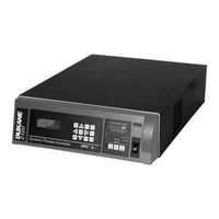
Dukane DPC II Plus User Manual (190 pages)
Dynamic Processor Controller
Brand:
Dukane
| Category:
Welding System
| Size: 10.82 MB
Table of Contents
Able of
5
Table of Contents
5
Section 1 - Introduction
11
Before Operating
13
Read the Manual First
13
Caution and Warnings
13
Drawings Labels
13
Manual Organization
14
DPC-II Plus Overview
16
EZ Welder Overview
16
EZ Welder™ Overview
16
Key DPC-II Plus Features
17
Key EZ Welder Features
18
Key EZ Welder™ Features
18
Ection Safety Tips
19
Section 2 - Safety Tips
19
Health & Safety Tips
21
Plastics Health Notice
22
Electrical Grounding Safety
22
Figure 2-1 120Volt, Grounded, 3-Prong Receptacle
22
Figure 2-2 220Volt, Grounded, 3-Prong Receptacle
22
RFI Considerations
23
Figure 2-3 International 220/240V Grounding
23
Figure 2-4 Dpcgrounding Arrangement
23
Figure 2-5 Press Grounding Arrangement
23
Ection Unpacking & Installation
25
Section 3 - Unpacking & Installation
25
Shipping Carton Contents
27
DPC Placement
27
Benchtop
27
Figure 3-1 Installing a Benchtop DPC
27
Table 3-I Contents of DPC II Plus Shipping Container
27
Rack Mounting
28
Figure 3-2 Rack-Mounted DPC Using Bracket Kit
28
Rear Panel Overview
29
Ground the System
29
Figure 3-3 DPC II Plus and EZ Rear Panel & Optional Modules
29
Connect the Cables
30
Hand Probe System
30
Automated Probe System
30
Figure 3-4 DPC II Plus and EZ Hand Probe Cabling Connections
31
Figure 3-5 DPC II Plus and EZ Automated Probe Cabling Connections
31
Multiple Probe System
32
Figure 3-6 DPC II Plus Multiple Probe Cabling Connections
32
Automated Thruster System
33
Figure 3-7 DPC II Plus Automated Thruster Cabling Connections
33
Dukane Press System
34
Figure 3-8 DPC II Plus and EZ Press Cabling Connections
34
Emergency Stop Switch Interface
35
Rear Electrical Power Switch
35
Figure 3-9 Emergency Stop Switch Interface
35
Figure 3-10 Rear Panel AC Breaker Switch
35
Ection Controls & Displays
37
Section 4 - Controls & Displays
37
Front Panel Layout
39
Figure 4-1A DPC II Plus Control Panel Layout
39
Figure 4-1B DPC EZ Control Panel Layout
39
Generator Status Panel
40
Figure 4-2 Front Panel AC Power Section
40
Figure 4-3 Generator Control Keys
40
System Status Display
41
Figure 4-4 System Status Display
41
System Power Output Display
42
Figure 4-5 Power Output Display Normal Operation
42
Figure 4-6 Power Output Display Warning Indicators
42
Process Control
43
Process Control Keys
43
AC Power
40
Generator Status Section
40
Generator Control Keys
40
Process Control Panel
43
Menu Function Keys
43
Figure 4-7 Menu Keys
43
Figure 4-8A DPC II Plus GEN. INFO Menu Display
43
Figure 4-8B DPC EZ GEN. INFO Menu Display
43
Menu Display
45
Control Menu Display
45
Figure 4-9 Menu Display - Typical Selection Menu
45
Figure 4-10 Menu Display - Typical Confirmation Screen
45
Figure 4-11 Menu Display - Typical Data Entry Screen
45
Ection Rear Connectors
47
Section 5 - Rear Connectors
47
Rear Panel Layout
49
Figure 5-1 DPC II Plus and EZ Welder Rear Panel Connectors
49
System Input Connector
50
Figure 5-2 HD-15 System Input Connector
50
Figure 5-3 Cable End of System Input Connector
50
Table 3-II
50
Table 5-I System Input Connector Signals
50
Table 5-II
51
Table 5-III System Input Cable Color Code
51
System Output Connector
52
Figure 5-4 DB-25 System Output Connector
52
Table 5-IV System Output Connector Signals
52
Remote Amplitude Control
56
Figure 5-5 Remote Amplitude Control Module
56
Figure 5-6 Current Loop Transfer Function Graph
56
Power Output Module Option
57
Figure 5-7 Power Signal Output Module
57
Press Control Module Option
58
Figure 5-8 Press Control Module
58
Figure 5-9 Press Connector Pin Identification
58
Table 5-V J902 Press Base Connector Pinout
58
Table 5- VI J901 Thruster Connector Pinout
59
Multi-Probe Module Options
60
Figure 5-10 Master and Slave Multi-Probe Controller Modules
60
Jumper Block Options
61
Status Driver Normal Selection State
61
Status Driver Selection
61
Automation Cycle Stop or End of Weld
61
Switch Debounce Filter Time Delay
61
Timer Board Enable/Bypass
61
Card Slot and Jumper Block Locations
62
System Control Inputs
62
Figure 5-11 Card Slot, Connector & Jumper Block Locations
62
Jumper Block Details
63
Figure 5-12 Jumper Block Details
63
Section 6 - Menu Structure
65
Process Setup
67
Figure 6-1 DPC II Plus Startup Menu
67
Figure 6-2 DPC II Plus Configuration Menu
67
Figure 6-3 DPC II Plus Weld Cycle Display
67
Figure 6-4 DPC II Plus Process Setup Menu
67
Process Control
68
Figure 6-5 Process Setup Main Menu Structure
68
Figure 6-6 Process Control Menu Flowchart
69
Process Limits
70
Figure 6-7 Limit Definition Menu Flowchart
70
Utilities
71
Figure 6-8 Utilities Menu Flowchart
71
Ection Process Control Menu
73
Section 7 - Process Setup Menu
73
Hand Probe
75
Figure 7-1 DPC II Plus Startup Menu
75
Figure 7-2 DPC II Plus Configuration Menu
75
Figure 7-3 DPC II Plus Time Weld Cycle Display
75
Figure 7-4 DPC II Plus Energy Weld Cycle Display
75
Untimed Hand Probe
76
Timed Hand Probe
76
Figure 7-5 Process Setup Menu
76
Figure 7-6 Process Control Trigger Method Menu
76
Figure 7-7 Hand Probe Flow Chart
76
Timed Hand Probe - Energy
77
Figure 7-8 Hand Probe Weld Method Menu
77
Figure 7-9 Hand Probe Weld Time Menu
77
Figure 7-10 Hand Probe Weld Energy Menu
77
Figure 7-11 Hand Probe Maximum Weld Time Menu
77
MPC Probe
78
Auto Stop Option
78
Untimed MPC Probe - Probe Delay
78
Figure 7-12 Multi-Probe Controller Flowchart
78
Figure 7-13 Auto Stop Weld Menu
78
Weld Method - Time
79
Figure 7-14 Probe Time Delay Menu
79
Figure 7-15 Weld Method Selection Menu
79
Figure 7-16 MPC Probe Weld Time Menu
79
Weld Method - Energy
80
Weld Method - Ground Detect
80
Figure 7-17 MPC Probe Weld Energy Menu
80
Figure 7-18 MPC Probe Maximum Weld Time
80
Figure 7-19 Ground Detect Fixture Isolation
80
Auto Probe
81
Figure 7-20 Ground Detect Scrub Time Data Entry
81
Auto Stop Option
82
Auto Probe
82
Figure 7-21 Auto Probe Setup Flowchart
82
Untimed Auto Probe - Delay
83
Timed Auto Probe - Weld Method
83
Holdtime
83
Afterburst
83
Figure 7-22 Process Control Weld Method Selection
83
Figure 7-23 Process Control Hold Time Selection
83
Figure 7-24 Auto Probe Hold Time Data Entry Screen
83
Figure 7-25 Auto Probe Afterburst Selection Menu
83
Figure 7-26 Auto Probe Afterburst Enable Menu
83
Figure 7-27 Auto Probe Afterburst Delay Data Entry
84
Figure 7-28 Auto Probe Afterburst Duration Data Entry
84
Figure 7-29 Process Setup Menu
84
Press Mode
85
Figure 7-30 Press/Auto Probe Setup Flowchart
85
Initiate Mode
86
Auto Stop
86
Head up on Auto Stop
86
Trigger Type
86
Single/Dual Pressure Mode
86
Press Mode Example
87
Figure 7-31 Startup Welding Cycle Data Screen
87
Figure 7-32 Mode and Enter Menu Keys
87
Figure 7-33 Process Setup Menu
87
Figure 7-34 Press Trigger Method Menu
87
Figure 7-35 Press Initiate Mode Menu
88
Figure 7-36 Press Trigger Type Menu
88
Figure 7-37 First Pass through Process Control Menu
88
Figure 7-38 Single or Dual Pressure Selection Menu
88
Figure 7-39 Pressure One Weld Method Selection Menu
88
Figure 7-40 Pressure One Weld Time Data Entry
88
Figure 7-41 Pressure Two Weld Method Selection Menu
89
Figure 7-42 Pressure Two Weld Energy Data Entry
89
Figure 7-43 Pressure Two Max Weld Time Data Entry
89
Figure 7-44 Dual Pressure Time Only Menus
89
Figure 7-45 Second Pass through Process Control Menu
89
Figure 7-46 Press Hold Time Data Entry
90
Figure 7-47 Third Pass through Process Control Menu
90
Figure 7-48 Press Afterburst Enable Menu
90
Figure 7-49 Press Afterburst Delay Data Entry
90
Figure 7-50 Press Afterburst Duration Data Entry
90
Figure 7-51 Return to Process Control Menu
90
Hot Keys
91
Figure 7-52 Process Setup Menu
91
Figure 7-53 Dual Pressure Welding Cycle Data
91
Figure 7-54 Hot Keys
91
Figure 7-55 Min and Max Values for Hold Time
91
Figure 7-56 Modified Hold Time
91
Process Control Recap
92
Figure 7-57 Amplitude Adjust
92
Figure 7-58 Process Control Menu Flowchart
93
Table 7-I Process Control Menu Listing
94
Table 7-II Parameter Min-Max Values
95
Ection Process Limits Menu
97
Section 8- Process Limits Menu
97
Process Limits Menu
99
Table 8-I Recognized Limits in a Dual-Pressure Mixed-Mode Welding Cycle
99
Table 8-II
99
Table 8-III Recognized Limits in a Single-Pressure Welding Cycle
99
Limit Definition
100
Suspect and Bad Limits
100
Process Limits
100
Figure 8-1 Process Setup Main Menu
100
Figure 8-2 Limit Definition Menu
100
Figure 8-3 Single Pressure Process Limits Menu
100
Single Pressure Mode
101
Figure 8-4 Limit Definition Flowchart
101
Figure 8-5 Dual Pressure Process Limits Menu
101
Dual Pressure Mode
102
Figure 8-6 Single Pressure Max Energy Data Entry
102
Figure 8-7 Minimum Value Error Message
102
Figure 8-8 Dual Pressure Limits Selection Menu
102
Figure 8-9 P1 Maximum Energy Data Entry
102
Figure 8-10 CANCEL Key Return Path Flow Chart
103
Ection Utilities Menu
105
Section 9 - Utilities Menu
105
Setup Utilities
107
Figure 9-1 Utilities Menu Flowchart
107
Select Setup
108
Figure 9-2 Process Setup Main Menu
108
Figure 9-3 Setup Utilities Menu
108
Figure 9-4 Setup Utilities Selection Menu
108
Figure 9-5 Setup Types Selection Menu
108
Figure 9-6 Enter New Setup Menu
108
Figure 9-7 New Setup Configuration Message
108
Copy a Setup
109
Erase Setups
109
Figure 9-8 Source File Location Entry
109
Figure 9-9 Destination File Location Entry
109
Figure 9-10 Confirm Copy Files
109
Figure 9-11 Erase Setups Selection Menu
109
Figure 9-12 Confirm Erase Selected Setup
109
Figure 9-13 Erase Setup in Progress
109
Part Count
110
Reset Part Count
110
Count Suspect/Bad Parts
110
Figure 9-14 Confirm Erase All Setups
110
Figure 9-15 Erasing All Setups in Process
110
Figure 9-16 Part Count Selection Menu
110
Figure 9-17 Confirm Reset Part Count
110
Figure 9-18 Confirm Counter Enabled
110
Preset Part Count
111
Status Outputs
111
Cycle Press off Line
111
Figure 9-19 Counter Preset Value
111
Figure 9-20 Status Output Mode Selection
111
Figure 9-21 Cycle Press Selection Menu
111
Ection Probes & Probe Stacks
113
Section 11 - Probes/Probe Stacks
113
The Ultrasonic Probe
115
Theory of Operation
115
Probe Configuration
115
Figure 10-1 Hand Probe, Horn and Replaceable Tip
115
Ultrasonic Horn
116
Booster
116
Figure 10-2 Probe with Booster and Horn
116
Stack Assembly
117
Installing Replaceable Tips
117
Figure 10-3 Replaceable Tip Installation
117
Mounting Stud to Horn/Booster
118
Table 10-I Stud Torque Unit Conversions
118
Horn to Booster
119
Booster to Probe
119
Horn to Probe
119
Figure 10-4 Stack Assembly Procedure
119
Torque Unit Conversion Chart
120
Figure 10-5 Torque Value Conversion Graph
120
Table 10-II Horn/Booster Torque Unit Conversions
120
Stack Disassembly
121
Figure 10-6 Hand Probe Assembly and Disassembly
121
Figure 10-7 Probe Stack with Booster Assembly and Disassembly
122
Figure 10-8 Separating the Horn from the Booster
123
Booster Notes
124
Figure 10-9 Removing Replaceable Tip from Horn
124
Stack Mounting
125
Section 11 - DPC Checkout
127
Startup and Self-Test
129
Figure 11-1 Front Panel Startup Controls and Indicators
129
System Test
130
Figure 11-2 System Test Controls and Indicators
130
Probe Operation
131
Stopping the Weld Cycle
131
Manual Systems
131
Automated System
131
End of Day
131
Figure 11-3 Stopping the Weld Cycle
131
Ection Troubleshooting
133
Section 12 - Troubleshooting
133
No Ultrasonic Output
135
Probe
135
Cable
135
Figure 12-1 Rear Ultrasound and System in Connectors
135
Generator
136
Operate Input
136
Figure 12-2 Generator on LINE Key and Indicator
136
Generator Faults
137
OVERLOAD Indicator
137
OVERTEMP Indicator
137
FAULT Indicator
137
Figure 12-3 Troubleshooting Flowchart - Part 1
137
Generator Errors
138
INPUT TEST Indicator
138
TEST Control Key
138
Figure 12-4 Troubleshooting Flowchart - Part 2
138
Troubleshooting Flowchart
139
Error Messages
141
Ection Care & Maintenance
143
Section 13 - Care & Maintenance
143
Front Panel
145
Rear Panel
145
Chasis
145
Figure 13-1 Location of DPC Air Cooling Vents
145
Stack Surfaces
146
Stack Maintenance
146
Stack Inspection
146
Even Contact
146
Uneven Contact
146
Figure 13-2 Location of Stack Mating Surfaces
146
Figure 13-3 Flat Surface with Even Contact
146
Figure 13-4 Surface with Uneven Contact
146
Crowning
147
Center Depression
147
Corrosion
147
Figure 13-5 Crowned Surface
147
Figure 13-6 Center Depression
147
Probe Reconditioning
148
Overview
148
Machining the Mating Surfaces
148
Manual Resurfacing
148
Reconditioning
148
Figure 13-7 Manual Resurfacing
149
Section 14 - Contacting Dukane
151
Ultrasonics Division Main Office
153
Identify Equipment
153
Our Website
153
Email Addresses
154
Telephone Extensions
154
Section 15 - Specifications
155
Regulatory Compliance
157
Federal Communications Commission
157
CE Marking (Conformité Europeéne)
157
Dimensions
158
Operating Enviornment
158
Figure 15-1 Generator 3-View and Dimensions
158
Power Requirements
159
Table 15-IDPC II Plus Generator Models and Power Supply Requirements
159
Table 15-II DPC EZ Generator Models and Power Supply Requirements
159
Interpreting the DPC Model Number
160
Figure 15-2 Interpreting the DPC II Plus Model Number
160
Section 16 - Warranty
161
Domestic Warranty
163
International Warranty
164
Ppendix List of Figures
165
Appendix A - List of Figures
165
Appendix B - List of Tables
169
Appendix C - User Supplied Circuitry
171
Manual Switch Circuit
173
Figure C-1 Manual Control Switch
173
Input Connector
173
Automation Switch Circuits
174
Figure C-2 Automation Control Switches
174
Isolated Automation Controls
175
Figure C-3 Non-Isolated Current Sink Switch
175
Non-Isolated Switch Circuits
175
Current Sink
175
Current Sink
176
Figure C-4 Non-Isolated Current Source Switch
176
Current Source
176
Current Source
177
Figure C-5 Isolated Current Source Circuit
177
Isolated Switch Circuit
177
Index
179
Advertisement
Dukane DPC II Plus Application Note (10 pages)
Automation Interface Requirements for the System Input Interface of a DPC II / II+ Welding System
Brand:
Dukane
| Category:
Welding System
| Size: 0.68 MB
Advertisement
Related Products
Dukane DPC II
Dukane DPC 4
Dukane DP3630
Dukane DK120
Dukane DK130
Dukane DK140
Dukane Digital-Multimedia Projector None
Dukane DVP508
DUKANE DC80A
Dukane DVP509
Dukane Categories
Projector
Document Camera
Welding System
Monitor
Power Supply
More Dukane Manuals
Login
Sign In
OR
Sign in with Facebook
Sign in with Google
Upload manual
Upload from disk
Upload from URL