Sign In
Upload
Manuals
Brands
Dodge Manuals
Automobile
2001 Ram 1500
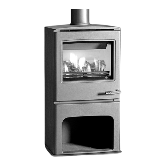
Dodge 2001 Ram 1500 Manuals
Manuals and User Guides for Dodge 2001 Ram 1500. We have
1
Dodge 2001 Ram 1500 manual available for free PDF download: Owner's Manual
Dodge 2001 Ram 1500 Owner's Manual (2890 pages)
Brand:
Dodge
| Category:
Automobile
| Size: 67.68 MB
Table of Contents
Table of Contents
2
Body Code Plate
2
Fastener Identification
4
Bolt Markins and Torque - Metric
5
Bolt Marking and Torque Values - US Customary
5
How to Determine Bolt Strength
6
Fastener Usage
7
International Vehicle Control & Display Symbols
7
Metric System
7
Conversion Formulas and Equivalent Values
8
Common Metric Equivalents
8
Torque References
10
Specified Torque for Standard Bolts
10
Veci Label Description
11
Veci Label Operation
11
Vehicle Identification Number
11
Vin Coding/Locations
11
Vehicle Safety Certification Label
13
Equipment Identification Plate
13
Lubrication & Maintenance
14
Description - Fuel Requirements - Gas Engines
14
Reformulated Gasoline
14
Gasoline/Oxygenate Blends
14
Sulfur in Gasoline
15
Materials Added to Fuel
15
Fuel System Cautions
15
Description - Fuel Requirements - Diesel Engine
15
Parts & Lubricant Recommendation
16
Fluid Types
16
Standard Procedure - Classification of Lubricants
16
Description - Engine Oil
16
Energy Conserving Oil
17
Container Identification
17
Api Service Grade Certified
17
Sae Viscosity
17
Description - Transfer Case Fluid
18
Description - Automatic Transmission Fluid
18
Fluid Additives
18
Operation - Automatic Transmission Fluid
18
Fluid Capacities
19
Maintenance Schedules
20
Light Duty Engine
20
Emission Control System Maintenance
20
Fluid Fill Locations and Lubrication Points
20
Description - Medium Duty Truck Maintenance Schedule
26
Jump Starting
40
To Jump Start a Disabled Vehicle
40
Jumper Cable Clamp Connections
40
Hoisting
41
Floor Jack
41
Safety Stands
41
Towing
42
Vehicle Lifting Locations
42
Front Lift Pad Location
42
Tow Vehicles with Approved Equipment
42
Ground Clearance
43
Ramp Angle
43
Towing When Keys Are Not Available
43
Four-Wheel-Drive Vehicle Towing
43
Suspension
44
Wheel Alignment
44
Diagnosis and Testing - Pre-Alignment
45
Standard Procedures - Alignment I.F.S.
45
Alignment Angles - Link/Coil
45
Standard Procedures - Caster Correction Measurement
46
Caster Camber Adjustment Location
46
Corrected Caster Chart-Cab Chassis
48
Standard Procedures - Alignment Link/Coil Suspension
48
Toe Position
48
Adjustment Cam
48
Front - 2Wd
50
Table of Contents
50
Torque Chart
51
Torque Specifications
51
Independent Front Suspension
51
Description
51
Hub / Bearing
52
Special Tools
52
Removal
52
Installation
52
Jounce Bumper Description
52
Operation
52
Knuckle Description
52
Operation
53
Removal
53
Installation
53
Lower Ball Joint Diagnosis and Testing
53
Lower Control Arm Removal
53
Shock Description
54
Operation
54
Diagnosis and Testing
54
Removal
54
Installation
54
Spring Description
54
Stabilizer Bar Operation
55
Stabilizer Bar Removal
55
Diagnosis and Testing - Upper Ball Joint
55
Coil Spring
55
Upper Control Arm Removal
56
Upper Control Arm Installation
56
Front - 4Wd
57
Link/Coil Suspension
58
Special Tools
59
Hub / Bearing
59
Rotor, Hub/Bearing and Stud
61
Hub Spacer
61
Brake Shield
61
Brake Shield with Wheel Speed Sensor
62
Hub Bearing Mounting Bolts
62
Removal
63
Installation
63
Description
63
Operation
63
Knuckle Description
63
Lower Control Arm
63
Cam Adjuster
64
Shock Absorber and Bracket
64
Removal
64
Installation
64
Shock Description
64
Operation
64
Stabilizer Bar
65
Shock Absorber Axle Mount
65
Track Bar Operation
66
Track Bar Removal
66
Dial Indicator Location
66
Stabilizer Link
66
Diagnosis and Testing
66
Lower Ball Joint Removal
67
Track Bar Puller
67
Upper and Lower Suspension Arm
67
Lower Snap Ring
67
Upper Ball Joint Removal
68
Upper Ball Joint Installation
68
Rear Description
69
Diagnosis and Testing - Spring and Shock
69
Spring and Shock Absorber
70
Rear Description
70
Specifications
70
Suspension-Rear
71
Shock
71
Removal
71
Installation
71
Spring Description
71
Operation
71
Special Tools
71
Bushings Removal
71
Jounce Bumper
71
Description
71
Rear Spring - 4X2
72
Rear Spring - 4X4
72
Rear Spring - Cab-Chassis 11000 GVW
72
Spring Description
72
Stabilizer Bar Description
73
Operation
73
Removal
73
Installation
73
Description
73
Differential & Driveline
74
Propeller Shaft Description
74
Propeller Shaft Operation
74
Installation
74
Front Propeller Shaft
75
Rear Propeller Shaft with Center Bearing
75
Diagnosis and Testing - Propeller Shaft Vibration
76
Rear Propeller Shaft - Dana Axles
76
Rear Propeller Shaft - Corporate Axles
76
Propeller Shaft and Yoke
76
Driveline Vibration
77
Balance
77
Runout
78
Runout Specifications
78
Clamp Screw at Position 1
78
Two Clamp Screws at the same Position
78
Two-Piece Propeller Shaft
79
Front (Output) Angle Measurement
79
Propeller Shaft Angle Measurement
79
Rear (Input) Angle Measurement
79
Universal Joint Angle Example
80
Universal Joint Angle Two-Piece Shaft
80
Propeller Shaft - Front Removal
81
Propeller Shaft - Front Installation
81
Rear Axle
81
Description
81
Propeller Shaft - Rear Removal
82
Propeller Shaft - Rear Installation
82
Center Bearing
82
Rear Propeller Shaft—Dana Axles
82
Center Bearing Operation
83
Center Bearing Removal
83
Center Bearing Installation
83
Center Bearing Adjustment
83
Description
83
Single Cardan Universal Joints
84
Remove Snap Ring
84
Press out Bearing
84
Press out Remaining Bearing
84
Disassembly
84
Front Axle - 216Fbi Description
85
Front Axle - 216Fbi Operation
85
Diagnosis and Testing - Axle
86
Gear Noise
86
FBI Differential Cover
86
Differential Operation-Straight Ahead Driving
86
Bearing Noise
87
Low Speed Knock
87
Driveline Snap
87
Pinion Gear ID Numbers
90
Pinion Gear Depth Variance
91
Pinion Depth Measurement and Adjustment
91
Adjustment Shim Loactions
91
Pinion Gear Depth Gauge Tools
92
Pinion Height Block
92
Gauge Tools in Housing
92
Differential Side Bearing Preload and Gear Backlash
93
Shim Selection
93
Pinion Gear Depth Measurement
93
Bearing Cap Bolts
93
Seat Pinion Gear Side Dummy Bearing
94
Seat Ring Gear Side Differential Dummy Bearing
94
Differential Side Play Measurement
94
Differential Case to Ring Gear Side
95
Differential Case to Pinion Gear Side
95
Gear Contact Pattern
96
Ring Gear Backlash Measurement
96
Backlash Shim
96
Axle Shafts Removal
101
Axle Shafts Installation
101
Axle Shafts - Intermediate Removal
101
Axle Shafts - Intermediate Installation
101
Axle Shaft Seals
102
Axle Vacuum Motor
102
Vacuum Control System
103
Diagnosis and Testing - Vacuum Motor
104
Axle Vacuum Shift Motor
104
Shift Motor Housing
106
Shift Motor Components
106
Pinion Seal
107
Axle Shaft U-Joint
107
Yoke Bearing Cap
107
Pinion Yoke
108
Pinion Seal Installer
108
Pinion Yoke Installer
108
Pinion Rotation Torque
108
Differential
109
Pinion Shaft Nut
109
Bearing Cap Reference
109
Spread Differential Housing
109
Differential Removal
110
Pinion Mate Shaft
110
Pinion Mate/Side Gear
110
Pinion Mate Shaft Roll-Pin
111
Differential Case
111
Differential Case Bearings
112
Differential Cover
112
Differential Bearing Puller
112
Pinion Gear/Ring Gear
113
Differential Bearing Installer
113
Ring Gear
113
Pinion Gear
114
Front Pinion Bearing Cup
114
Rear Pinion Bearing Cup
114
Collapsible Spacer
114
Rear Pinion Bearing
115
Collapsible Preload Spacer
116
Tightening Pinion Nut
117
Pinion Rotating Torque
117
Ring Gear Bolt
117
Front Axle - 248Fbi
118
Front Axle - 248Fbi Description
119
Diagnosis and Testing
119
Removal
123
Installation
123
Adjustments
123
Specifications
131
Special Tools
131
Axle Shafts
133
Axle Shafts - Intermediate
133
Axle Shaft Seals
134
Removal
134
Installation
134
Axle Vacuum Motor
135
Description
135
Operation
135
Vacuum Motor
138
Removal
138
Disassembly
138
Assembly
138
Installation
138
Single Cardan Universal Joints
138
Installation
139
Pinion Seal
139
Removal
139
Differential Removal
141
Disassembly
141
Assembly
142
Installation
142
Rear Axle - 9 1/4
150
Differential Cover 9 1/4 Inch Axle
152
Differential Operation - Straight Ahead Driving
152
Trac-Lok Differential
153
Differential Operation - on Turns
153
Trac-Lok Limited Slip Differential
153
Rear Axle - 248Rbi
182
Rear Axle - 267Rbi
213
Differential Case Bearings Removal
237
Installation
237
Pinion Gear/Ring Gear
238
Removal
238
Installation
239
Rear Axle - 286Rbi
242
Description
242
Operation
242
Diagnosis and Testing
244
Axle
246
Removal
246
Installation
247
Adjustments
247
Specifications
255
Special Tools
255
Axle Shafts Removal
258
Installation
258
Removal
258
Axle Bearings Removal
258
Rear Axle
258
Pinion Seal
258
Installation
261
Differential Removal
261
Disassembly
261
Assembly
261
Differential - Trac-Lok
263
Disassembly
263
Assembly
263
Differential Case Bearings Removal
265
Installation
265
Pinion Gear/Ring Gear/Tone Ring Removal
266
Installation
268
Brakes
272
Brakes - Base Specifications
273
Brakes - Base Torque Chart
274
Base Brakes Special Tools
275
Hydraulic/Mechanical Description
275
Diagnosis and Testing - Base Brake System
276
Preliminary Brake Check
276
Road Testing
276
Warning
276
Pedal Falls Away
277
Low Pedal
277
Spongy Pedal
277
Hard Pedal or High Pedal Effort
277
Rear Brake Grab or Pull
278
Brake Lining Contamination
278
Wheel and Tire Problems
278
Brake Noises
278
Brake Lines
279
Standard Procedure - Pressure Bleeding
279
Standard Procedure - Double Inverted Flaring
279
Standard Procedure - Iso Flaring
279
Combination Valve Description
280
Combination Valve Operation
280
Pressure Differential Switch
280
Metering Valve
280
Diagnosis and Testing
280
Disc Brake Calipers
281
Pressure
281
Rear Caliper
281
Removal
281
Installation
281
Caliper
282
C-Clamp One Piston
282
Protect Caliper Piston
282
Disassembly
282
Piston Dust Boot Removal
283
Piston Seal
283
Bushings and Boot Seals
283
Cleaning
283
Inspection
283
Assembly
283
Polishing Piston Bore
284
Caliper Piston Installation
284
Seating Dust Boot
284
Fluid
285
Diagnosis and Testing - Brake Fluid Contamination
285
Standard Procedure - Brake Fluid Level
285
Rear Caliper Install
285
Fluid Reservoir Removal
286
Fluid Reservoir Installation
286
Loosening Reservoir
286
Brake Fluid Contamination
286
Pedal Description
287
Pedal Operation
287
Pedal Removal
287
Grommet Removal
287
Power Brake Booster
288
Diagnosis and Testing - Hydraulic Booster
288
Noises
288
Clunk-Chatter-Clicking
288
Installation
288
Seal Leakage
289
Hydraulic Booster Diagnosis Chart
289
Hydraulic Booster Seals
289
Standard Procedure - Bleeding
290
Master Cylinder and Booster
290
Booster Push Rod
290
Hydraulic Booster
290
Power Brake Booster
290
Removal
290
Diagnosis and Testing—Disc Brake Rotor
291
Rotor Minimum Thickness
291
Rotor Runout
291
Rotor Thickness Variation
291
Installation
291
Checking Rotor Runout and Thickness Variation
292
Measuring Rotor Thickness
292
Rotor / Hub Removal
292
Caliper Adapter Assembly
292
Rotor to Hub
293
Installation
293
Brake Pads/Shoes
294
Rotor / Pads/ Caliper
294
Inboard Brake Shoe
294
Outboard Brake Shoe
294
Top Anti-Rattle Spring
295
Bottom Anti-Rattle Spring
295
REMOVAL - REAR BRAKE SHOES-11 Inch
296
Installation
298
Master Cylinder Description
300
Operation
300
Diagnosis and Testing
300
Master Cylinder/Power Booster
300
Master Cylinder Bleeding
301
Removal
301
Installation
301
Wheel Cylinders
302
Removal
302
Disassembly
302
Cleaning
302
Inspection
302
Assembly
302
Support Plate
303
Drum
303
Wheel Cylinder Mounting Surface
303
Installation
303
Removal
303
Description
303
Operation
303
Diagnosis and Testing - Brake Drum
304
Brake Drum Runout
304
Standard Procedure - Brake Drum Machining
304
Inspection
304
Adjustment - Rear Brake Drum
305
Adjustment with Brake Gauge
305
Shoe Contact Surfaces
305
Adjusting Gauge on Drum
305
Parking Brake
306
Adjustment with Adjusting Tool
306
Description
306
Parking Brake Pedal Assembly
307
Operation
307
Removal
307
Installation
307
Cables
308
Removal - Front Parking Brake Cable
308
Lock out Parking Cable
308
Disengagement of Cable
308
Removal - Rear Park Brake Cables
309
Installation - Rear Park Brake Cable
309
Cables and Tensioner
309
Installation - Front Parking Brake Cable
310
Cable Tensioner
311
Release
311
Adjustment Mark
311
Removal
311
Shoes
312
Park Brake Release Handle Remove/Install
312
Installation - Rear Drum in hat Park Brake Shoes - 2500/3500
313
Shoes Removal
313
Shoe Assembly
313
Clutch
314
Diagnostic and Testing - Clutch
315
Clutch Contamination
315
Engine Powerflow
315
Clutch Operation
315
Clutch Components and Inspection
316
Improper Release or Clutch Engagement
317
Clutch Misalignment
317
Clutch Flywheel Runout
317
Clutch Cover and Disc Runout
317
Clutch Diagnosis Chart
318
Specifications - Clutch
320
Clutch Disc
320
Description
320
Clutch Disc-V6 Engine
321
Clutch Disc-V8 Engine
321
Clutch Disc-V10/Diesel Engines
321
Removal
321
Supporting Engine with Jack Stand and Wood Block—Diesel Model Shown
322
Marking Clutch Cover Position
322
Clutch Cover Bolt Loosening/Tightening Pattern
322
Clutch Disc and Cover Alignment/Installation
322
Clutch Release Component Lubrication Points
323
Input Shaft Lubrication Points
323
Release Fork and Bearing Spring Clip Position
323
Clutch Housing
323
Clutch Housing
324
Diagnosis and Testing - Clutch Housing
324
Measuring Clutch Housing Bore Runout
324
Dial Indicator Mounting Stud or Rod
324
Housing Bore Measurement Points and Sample Readings
325
Housing Bore Alignment Dowel Selection
325
Measuring Clutch Housing Face Runout
325
Housing Face Measurement Points and Sample Readings
326
Housing Face Alignment Shims
326
Removal
326
Installation
326
Clutch Release Bearing
327
Transmission/Clutch Housing - NV4500
327
Clutch Housing Installation - NV4500
327
Description
327
Operation
327
Clutch Release Components
328
Removal
328
Installation
328
Pressure Plate Description
328
Flywheel
329
Pressure Plate - V6/V8 Gas Engine
329
Pressure Plate - V10/Diesel Engine
329
Operation
329
Description
329
Diagnosis and Testing - Flywheel
330
Pilot Bearing
330
Disassembly
330
Assembly
330
Description
330
Clutch Pedal
331
Typical Method of Installing Pilot Bearing
331
Clutch Cylinder Push Rod Attachment
331
Operation
331
Removal
331
Installation
331
Linkage
332
Knee Bolster Removal—Typical
332
Clutch/Brake Pedal Mounting
332
Installation
332
Description
332
Clutch Hydraulic Linkage
333
Operation
333
Removal
333
Installation
333
Clutch Slave Cylinder
334
Clutch Pedal Position (Interlock) Switch
335
Description
335
Operation
335
Cooling
336
Description—Cooling System Flow - 3.9L/5.2L/5.9L Engine
336
Description—Cooling System Flow - 5.9L Diesel
336
Description—Hose Clamps
337
Operation—Hose Clamps
337
Engine Cooling System Flow
337
Cooling System Components 5.9L Diesel Engine
337
Cooling System Circulation—Diesel Engine
338
Operation—Cooling System
339
Diagnosis and Testing - Preliminary Checks
339
Engine Cooling System Overheating
339
Diagnosis and Testing—On-Board Diagnostics (Obd)
339
Diagnosis and Testing—Cooling System Leaks
340
Erasing Trouble Codes
340
Ultraviolet Light Method
340
Pressure Tester Method
340
Internal Leakage Inspection
341
Combustion Leakage Test—Without Pressure Tester
341
Diagnosis and Testing - Cooling System Gas Engine
342
Standard Procedure—Draining Cooling System 5.9L Diesel Engine
350
Standard Procedure—Refilling Cooling System 5.9L Diesel Engine
350
Standard Procedure—Adding Additional Coolant
351
Standard Procedure—Coolant Level Check
351
Standard Procedure—Cooling System Cleaning/Reverse Flushing
351
Reverse Flushing
351
Reverse Flushing Engine
352
Chemical Cleaning
352
Standard Procedure—Coolant Selection-Additives
352
Accessory Drive
354
Belt Tensioners - 3.9L/5.2L/ 5.9L
354
Belt Tensioners - 8.0L
355
Tensioner Indexing Marks and Mounting Nut
355
Belt Tensioner—8.0L V-10 Engines
356
Indexing Marks—8.0L Engines Typical
356
Belt Tensioner
357
Tensioner Dowel Pin
357
Belt Tensioners - 5.9L Diesel
358
Tensioner Dowel Hole
358
Belt
358
Diagnosis and Testing—Accessory Drive Belt
359
Visual Diagnosis
359
Noise Diagnosis
359
Automatic Belt Tensioner Diesel Engine—Typical
359
Accessory Drive Belt Diagnosis Chart
360
Belt Tensioner—5.2L/5.9L Gas Engines
361
Belt Routing—5.2L/5.9L Engines with A/C
362
Belt Routing—5.2L/5.9L Engines Without A/C
362
Belt Wear Patterns
363
Belt Routing—With A/C
365
Diagnosis and Testing—Vacuum Pump Output
370
Diagnosing Low Vacuum Output Condition
370
Diesel Vacuum & Power Steering Pump Assembly
370
Vacuum Pump Oil Feed Line
371
Vacuum Pump Mounting
371
Pump Assembly Upper Mounting Bolt
371
Adapter to Power Steering Pump Nuts
372
Steering Pump, Vacuum Pump and Adapter
372
Pump Mounting Flange Gasket
372
Engine
374
Coolant
375
Ethylene-Glycol Mixtures
375
Propylene-Glycol Mixtures
375
Coolant Reserve/Overflow Tank
376
Description
376
Operation
376
Coolant Recovery Container - 3.9L/5.2L/ 5.9L/5.9L Diesel Description
376
Operation
377
Removal
377
Coolant Recovery Container - 8.0L
377
Description
377
Radiator Fan - 3.9L/5.2L/5.9L/8.0L
377
Using Special Tool 6958 Spanner Wrench
378
Fan Blade/Viscous Fan Drive—Gas Engines
378
Cleaning
378
Inspection
378
Installation
378
Radiator Fan - 5.9L Diesel
379
Fan Blade/Viscous Fan Drive
379
Removal
379
Cleaning
379
Inspection
379
Engine Block Heater - 3.9L/5.2L/5.9L Description
380
Installation
380
Operation
380
Removal
380
Engine Block Heater - 8.0L
381
Description
381
Operation
381
Removal
381
Installation
381
Engine Block Heater - 5.9L Diesel
382
Description
382
Operation
382
Removal
382
Installation
382
Engine Coolant Temp Sensor - 3.9L/5.2L/ 5.9L Description
383
Block Heater—Diesel Engine
383
Engine Coolant Temperature
383
Operation
383
Removal
383
Installation
383
Engine Coolant Thermostat - 3.9L/5.2L/5.9L
384
Diagnosis and Testing—Thermostat
384
Thermostat—5.2L and 5.9L Gas Powered Engines
384
Operation
384
Removal
384
Generator Support Bracket
385
Automatic Belt Tensioner
385
Spring Clamp Size Location
385
Installation
385
Thermostat—3.9L and 5.9L Engines
386
Thermostat Position—5.2L and 5.9L Engines
386
Belt Routing—5.2L and 5.9L Engines
386
Engine Coolant Thermostat - 8.0L
387
Description
387
Operation
387
Diagnosis and Testing
387
Removal
387
Thermostat Seal—8.0L V-10 Engine
388
Support Rod—8.0L V-10 Engine
388
Thermostat—8.0L V-10 Engine
388
Installation
388
Engine Coolant Thermostat - 5.9L Diesel
389
Engine Coolant Thermostat - 5.9L
390
Fan Drive Viscous Clutch
391
Diagnosis and Testing—Viscous Fan Drive
391
Description
391
Fan Drive Viscous Clutch - 5.9L DIESEL
392
Radiator - 3.9L/5.2L/5.9L
394
Diagnosis and Testing—Radiator
394
Coolant Flow
394
Removal
394
Coolant Recovery Bottle
395
Fan Shroud Mounting—3.9L/5.2L/5.9L
395
Typical Radiator Mounting
395
Cleaning
395
Radiator - 8.0L
396
Cross Flow Radiator—Typical
396
Inspection
396
Installation
396
Fan Shroud Mounting—8.0L Engine
397
Radiator - 5.9L Diesel
398
Coolant Recovery Bottle—Typical
399
Fan Shroud Mounting—5.9L Diesel Engine
399
Radiator Pressure Cap
400
Radiator Pressure Cap and Filler Neck
400
Description
400
Operation
400
Diagnosis and Testing—Radiator Cap-To-Filler Neck Seal
401
Diagnosis and Testing—Radiator Cap
401
Pressure Testing Radiator Cap
401
Cleaning
401
Inspection
401
Water Pump - 3.9L/5.2L/5.9L
402
Water Pump Location
402
Description
402
Operation
402
Typical Fan Shroud Mounting
403
Using Special Tool 6958 Spanner Wrench and Adapter Pins 8346
403
Fan Blade and Viscous Fan Drive
404
Belt Tensioner—3.9L V-6 or 5.2/5.9L V-8
404
Coolant Return Tube—3.9L V-6 or 5.2/5.9L V-8 Engines
404
Water Pump Bolts—3.9L V-6 or 5.2/5.9L V-8 Gas Engines—Typical
404
Cleaning
404
Inspection
404
Water Pump - 8.0L
405
Installation
405
Belt Tensioner—8.0L V-10 Engine
406
Water Pump Bolts—8.0L V-10
407
Water Pump O-Ring Seal—8.0L V-10
407
Cleaning
407
Inspection
407
Installation
407
Heater Hose Fitting Position
408
Water Pump - 5.9L Diesel
408
Description
408
Operation
408
Removal
408
Cleaning
408
Inspection
408
Water Pump Inlet Tube - 3.9L/5.2L/5.9L
409
Water Pump Removal/Installation
409
Pump O-Ring Seal
409
Generator—A/C Compressor Mounting Bracket—Typical
409
Idler Pulley—3.9L V-6 or 5.2/5.9L V-8 LDC-Gas Engines
410
Belt Tensioner—5.9L HDC-Gas Engine
410
Removal
410
Coolant Return
411
Coolant Return Tube—5.9L HDC-Gas Engine
411
Bracket Bolts—3.9L V-6 or 5.2/5.9L V-8 LDC-Gas
411
Bracket Bolts—5.9L HDC-Gas Engine
411
Removal—Water Pump Bypass Hose Without Air Conditioning
412
Installation—Water Pump Bypass Hose with Air Conditioning
412
Water Pump Bypass Hose—Typical
412
Tensioner Dowel Pin—5.9L HDC-Gas Engine
412
Installation—Water Pump Bypass Hose Without Air Conditioning
413
Tensioner Mounting
413
Transmission
414
Trans Cooler - 3.9L/5.2L/5.9L
414
Automatic Transmission Oil
415
Trans Cooler - 3.9L/5.2L/5.9L
415
Trans Cooler - 8.0L
417
Transmission Oil Cooler—3.9/5.2/5.9L Engines
417
Transmission Oil Cooler Thermostat Removal/Installation
417
Assembly
417
Description
417
Operation
417
Automatic Transmission Oil Cooler
418
Transmission Oil Cooler—8.0L Engine
419
Removal
419
Trans Cooler - 5.9L Diesel
420
Transmission Water-To-Oil Cooler
420
Auxiliary Transmission Oil Cooler
420
Description
420
Operation
420
Installation
420
Removal—Air to Oil Cooler
422
Removal—Water to Oil Cooler
422
Installation—Air to Oil Cooler
423
Transmission Water-To- Oil Cooler—Diesel
423
Audio
424
Central Timer Module
425
Diagnosis and Testing - Audio
425
Operation
425
Antenna Body & Cable
427
Antenna Nut Wrench C-4816
427
Special Tools
427
Description
427
Operation
427
Diagnosis and Testing - Antenna
428
Antenna Tests
429
Antenna Coaxial Cable Connector
429
Removal
429
Antenna Mounting
430
Antenna Mast Remove/Install - Typical
430
Antenna Cap Nut Remove/Install - Typical
430
Installation
430
Radio Choke Relay
431
Diagnosis and Testing - Radio Choke Relay
431
Description
431
Operation
431
Instrument Panel Antenna Cable
432
Filter, Choke, and Speaker Relay Remove/Install
432
Antenna Cable Routing
432
Removal
432
Installation
432
Radio
433
Diagnosis and Testing - Radio
433
Installation
433
Description
433
Operation
433
Radio Receiver Remove/Install
434
Removal
434
Radio Noise Suppression Components
435
Diagnosis and Testing - Radio Noise Suppression Components
435
Radio Receiver Connections
435
Installation
435
Description
435
Engine-To-Body Ground Strap
436
Engine-To-Body Ground Strap Remove/Install - V6 & V8 Engine
436
Removal
436
Installation
436
Cab-To- Bed Ground Strap
437
Heater Core Ground Strap Removal
437
Engine-To-Body Ground Strap Remove/Install - V10 Engine
437
Cab-To-Bed Ground Strap Remove/Install
437
Installation
437
Remote Switches
438
Heater Core Ground Strap Remove/Install
438
Remote Radio Switches
438
Installation
438
Description
438
Operation
438
Diagnosis and Testing - Remote Switches
439
Remote Radio Switch Test
439
Removal
439
Speaker
440
Remote Radio Switches Remove/Install
440
Installation
440
Description
440
Operation
440
Diagnosis and Testing - Speaker
441
A-Pillar Tweeter Speaker
442
A-Pillar Tweeter Remove/Install
442
Removal
442
Installation
442
Front Door Speaker
443
Front Door Speaker Remove/Install
443
Rear Speaker Remove/Install - Standard Cab
443
Removal
443
Installation
443
Rear Cab Side Panel Speaker Removal
443
Rear Door Speaker
444
Rear Speaker Remove/Install - Club Cab
444
Rear Door Speaker Remove/Install - Quad Cab
444
Installation
444
Removal
444
Chime/Buzzer
446
Chime Warning System
446
Fasten Seat Belt Warning
446
Diagnosis and Testing - Chime Warning System
447
Head/Park Lights-On Warning
447
Key-In-Ignition Warning
447
Warning Chime Support
447
Chime Warning System Diagnosis
448
Electronic Control Modules
452
Body Control/Central Timer Module
452
Central Timer Module (Base)
452
Central Timer Module (High-Line/Premium)
452
Body Control/Central Timer Module
453
Hard Wired Inputs
454
Hard Wired Outputs
454
Operation
454
Diagnosis and Testing - Central Timer Module
455
Messaging
455
Central Timer Module (Base) Remove/Install
456
Removal
456
Communication
457
Description - CCD Data Bus
457
Installation
457
Operation - CCD Data Bus
458
Bus (+) and Bus (–) Circuits
458
CCD Chips
458
Bus Bias and Termination
459
Bus Messaging
459
Bus Biasing
459
Bus Message Coding
460
Priority
460
Bus Termination
460
Message Identification
461
Transmission Verification
461
Message Arbitration
461
Voltage Cycling to Correspond to Message
461
Controller Antilock Brake
462
Diagnosis and Testing - CCD Data Bus
462
CCD Bus Failure
462
Bus Failure Visual Symptom Diagnosis
462
Description
462
Operation
462
Data Link Connector
463
Description - Data Link Connector
463
Operation - Data Link Connector
463
Harness Connector Locks
463
Removal
463
Installation
463
Engine Control Module
464
Engine Control Module (ECM) Location
464
Fuel Injection Pump Control Module (FPCM) Location
464
Powertrain Control Module
465
Engine Control Module (ECM) Location and Mounting
465
Description - Modes of Operation
465
Removal
465
Installation
465
Ignition Switch (Key-On) Mode
466
Engine Start-Up Mode
466
Engine Warm-Up Mode
466
PCM Location
466
Cruise Mode
467
Idle Mode
467
Acceleration Mode
467
Deceleration Mode
467
Description - 5 Volt Supplies
468
Description - Ignition Circuit Sense
468
Description - Power Grounds
468
Description - Sensor Return
468
Operation - Diesel
469
Operation - 5 Volt Supplies
470
Operation - Ignition Circuit Sense
470
PCM Location and Mounting
470
Engine Systems
472
Battery System
472
Diagnosis and Testing - Battery System
473
Operation
473
Battery System Description
473
Battery System Diagnosis
474
Abnormal Battery Discharging
475
Clean Battery Cable Terminal Clamp - Typical
476
Clean Battery - Typical
476
Cleaning
476
Inspection
476
Clean Battery Terminal Post - Typical
477
Specifications
477
Battery Description
477
Diagnosis and Testing - Battery
478
Low-Maintenance Battery - Typical
478
Operation
478
Standard Procedure - Checking Battery Electrolyte Level
479
Battery Caps - Export Battery
479
Standard Procedure - Battery Charging
480
Hook Inside Battery Cap Holes - Export Battery
480
Charging a Completely Discharged Battery
481
Charging Time Required
481
Charge Rate Table
481
Voltmeter
481
Standard Procedure - Built-In Indicator Test
482
Built-In Indicator
482
Standard Procedure - Hydrometer Test
483
Built-In Indicator Sight Glass Chart
483
Standard Procedure - Open-Circuit Voltage Test
484
Hydrometer
484
Standard Procedure - Load Test
485
Testing Open-Circuit Voltage - Typical
485
Volt-Ammeter-Load Tester - Typical
485
Open Circuit Voltage Table
485
Battery System
485
Standard Procedure - Ignition-Off Draw Test
486
Volt-Ammeter-Load
486
Remove Surface Charge from Battery
486
Load Test Temperature Table
486
Electronic Module Ignition-Off Draw (Iod) Table
487
Remove Battery Cable Terminal Clamp - Typical
488
Battery Cables - Typical
488
Battery Holddown
489
Operation
489
Removal
489
Installation
489
Battery Cable
490
Left Battery Hold Downs Remove/Install
490
Description
490
Diagnosis & Testing - Battery Cables
491
Operation
491
Voltage Drop Test
492
Fuel Shutdown Solenoid Connector
493
Test Battery Negative Connection Resistance - Typical
493
Test Battery Positive Connection Resistance
493
Test Battery Positive Cable Resistance
493
Negative Cable Removal - Gasoline
494
Positive Cable Removal - Gasoline
494
Positive Cable Installation - Gasoline
494
Test Ground Circuit
494
Negative Cable Installation - Gasoline
495
Battery Tray
495
Battery Tray - Typical
495
Description
495
Left Battery Tray Remove/Install - Typical for Right Battery Tray
496
Operation
496
Removal
496
Installation
496
Diagnosis and Testing - Charging
498
Charging Description
498
Generator Ratings
499
Specifications - Torque - Generator/Charging System
499
Battery Temperature Sensor
500
Battery Temperature Sensor Location
500
Operation
500
Description
500
Removal
500
Installation
500
Generator Description
500
Remove/Install Generator—3.9L/5.2L/5.9L
501
Remove/Install Generator—8.0L Engine
501
Remove/Install Generator—Diesel Engine
502
Generator Connectors—Typical Bosch
502
Generator Connectors—Typical Denso
502
Voltage Regulator Description
502
Operation
502
Starting
503
Diagnosis and Testing - Starting System
504
Testing
505
Cold Cranking Test
505
Starting System Diagnosis
505
Feed Circuit Test
506
Volts-Amps Tester Connections - Typical
506
Test Battery Positive Cable
507
Test Starter Ground - Typical
508
Control Circuit Testing
508
Specifications Starting System
509
Specifications - Torque - Starting System
509
Description
509
Engine Starter Motor Description
510
Diagnosis and Testing - Starter Motor
510
Starter Motor Solenoid
510
Operation
510
Continuity Test between Solenoid Terminaland Solenoid Case - Typical
511
Starter Motor Remove/Install - 3.9L/5.2L/5.9L Gasoline Engine
511
Removal
511
Starter Motor Wire Harness Remove/Install
512
Installation
512
Engine Starter Motor Relay
513
Diagnosis and Testing - Starter Relay
513
Description
513
Operation
513
Relay Circuit Test
514
Starter Relay
514
Power Distribution Center
514
Removal
514
Installation
514
Heated Systems
516
Heated Mirrors
516
Description - Heated Mirror System
516
Operation - Heated Mirror System
517
Diagnosis and Testing - Heated Mirror System
517
Heated Mirrors
517
Mirror Switch
518
Diagnosis and Testing - Heated Mirror Switch
518
Heated Mirror Switch
518
Description
518
Operation
518
Heated Mirror Grid
519
Diagnosis and Testing - Heated Mirror Grid
519
Description
519
Operation
519
Heated Seat System
520
Heated Seat System Switches
520
Diagnosis & Testing - Heated Seat System
521
Heated Seat System Self-Diagnosis
521
Driver Seat Heater Switch
522
Heated Seat Switches
522
Description
522
Operation
522
Diagnosis & Testing - Heated Seat Switch
523
Heated Seat Switch and Bezel Remove/Install
524
Heated Seat Switch Continuity
524
Removal
524
Installation
524
Heated Seat Cushion Trim Cover
525
Heated Seat Element Description
525
Operation
525
Diagnosis & Testing - Heated Seat Element and Sensor
526
Heated Seat Relay
526
Heated Seat Sensor
526
Description
526
Diagnosis & Testing - Heated Seat Relay
527
Relay Test
527
Passenger Seat Heater Switch
528
Heated Seat
528
Removal
528
Installation
528
Description
528
Operation
529
Horn
532
Diagnosis and Testing - Horn
533
Horns Remove/Install
533
Horn Description
533
Operation
533
Description
533
Removal
533
Horn Relay
534
Diagnosis and Testing - Horn Relay
534
Installation
534
Description
534
Operation
534
Horn Switch
535
Removal
535
Installation
535
Description
535
Driver Side Airbag Module Trim Cover and Horn Switch
536
Operation
536
Diagnosis and Testing
536
Removal
536
Ignition Control
538
Specifications - Torque - Ignition
539
Spark Plug Cable Order
539
Engine Firing Order
539
Automatic Shut down Relay
540
Spark Plug Cable Resistance
540
Ignition Coil Resistance—3.9L/5.2L/5.9L Engines
540
Operation - Asd Sense - Pcm Input
540
Description
540
ASD and Fuel Pump Relay Terminals
541
Camshaft Position Sensor
542
Power Distribution Center (PDC)
542
Camshaft Position Sensor (CMP) Location
542
CMP Sensor Location—8.0L V-10 Engine
542
Camshaft Position Sensor (CMP)
543
Notches at Rear of Camshaft Drive Gear
543
CMP Sensor Operation—8.0L V-10 Engine
544
CMP Location - Diesel
544
CMP R/I - Diesel
544
Replacing Old Sensor with Original
545
Replacing with New Sensor
545
Camshaft Position Sensor—Typical
545
CMP Location - 8.0L
545
Camshaft Sensor O-Ring—8.0L
546
Sensor Operation—8.0L V-10 Engine
546
Distributor
547
Replacing with a New Sensor
547
Sensor Depth Dimensions
547
Description
547
Distributor and Camshaft Position Sensor
548
Damper-To-Cover Alignment Marks—Typical
548
Operation
548
Removal
548
Installation
548
Distributor Cap
549
Diagnosis and Testing - Distributor Cap
549
Checking Distributor Position
549
Rotor Alignment Mark
549
Distributor Rotor
550
Ignition Coil
550
Diagnosis and Testing - Distributor Rotor
550
Cap Inspection—External—Typical
550
Ignition Coil Packs—8.0L V-10 Engine
551
Ignition Coil—3.9L V-6 or 5.2/5.9L V-8 LDC-Gas Engines
551
Ignition Coil—5.9L V-8 HDC-Gas Engine
552
Spark Plug
553
Diagnosis and Testing - Spark Plug Conditions
553
Spark Plug Cable Order—8.0L V-10 Engine
553
Normal Operation and Cold (Carbon) Fouling
553
Description
553
Cold Fouling/Carbon Fouling
554
Wet Fouling or Gas Fouling
554
Oil or Ash Encrusted
554
Scavenger Deposits
554
Chipped Electrode Insulator
555
Preignition Damage
555
Spark Plug Overheating
555
Heat Shields—3.9L/5.2L/5.9L Engines
556
Description
556
Operation
556
Cleaning
556
Installation
556
Spark Plug Cable Description
556
Spark Plug Cables
556
Removal
557
Installation
557
Engine Firing Order—5.2L/5.9L V-8 Engines
558
Engine Firing Order—3.9L V-6 Engine
558
Instrument Cluster
560
Instrument Cluster Components
561
Instrument Cluster Description
561
Instrument Cluster Operation
562
Gauges
563
Vacuum-Fluorescent Display
563
Indicators
564
Cluster Illumination
564
Diagnosis and Testing - Instrument Cluster
565
Chime Warning Requests
565
Actuator Test
566
Instrument Cluster Failure Message
567
Chime Warning Request Diagnosis
568
Cluster Illumination Diagnosis
568
Instrument Cluster Remove/Install
569
Removal
569
Gear Selector Indicator
570
Cluster Bulb
570
Gear Selector Indicator Remove/Install
570
Gear Selector Indicator Cable Remove/Install
570
Disassembly
570
Cluster Lens and Hood
571
Cluster Housing Rear Cover
571
Cluster Housing
571
Cluster Bulb Remove/Install
571
Assembly
572
Abs Indicator
573
Installation
573
Description
573
Operation
573
Airbag Indicator
574
Description
574
Operation
574
Brake/Park Brake Indicator
575
Diagnosis and Testing - Brake Indicator
575
Description
575
Operation
575
Check Gauges Indicator
576
Description
576
Operation
576
Cruise Indicator
577
Engine Oil Pressure Low Message
577
Cruise Lamp-On Message
577
Description
577
Operation
577
Engine Temperature Gauge Description
578
Engine Temperature Message
578
Engine Temperature Low Message
578
Engine Temperature High Message
578
Operation
578
Fuel Gauge
579
Description
579
Operation
579
Gear Selector Indicator
580
Description
580
Operation
580
High Beam Indicator Description
580
Diagnosis and Testing - High Beam Indicator
581
Indicator Does Not Illuminate with High Beams Selected
581
Indicator Stays Illuminated with High Beams Not Selected
581
Low Fuel Indicator
582
Bulb Test
582
Description
582
Operation
582
Malfunction Indicator Lamp (Mil)
583
Odometer
583
Description
583
Operation
583
Oil Pressure Gauge
584
Odometer/Trip Odometer Display Toggling
584
Trip Odometer Reset
584
Operation
584
Description
584
Engine Oil Pressure Message
585
Engine Oil Pressure High Message
585
Operation
585
Overdrive off Indicator Description
586
Operation
586
Seatbelt Indicator
586
Description
586
Service Reminder Indicator
587
Seatbelt Reminder Function
587
Driver Side Front Seatbelt Not Buckled
587
Description
587
Operation
587
Shift Indicator (Transfer Case)
588
Diagnosis and Testing - Four-Wheel Drive Indicator
588
Indicator Does Not Illuminate with Four-Wheel Drive Mode Selected
588
Description
588
Operation
588
Speedometer
589
Tachometer
589
Indicator Stays Illuminated with Four-Wheel Drive Mode Not Selected
589
Description
589
Operation
589
Transmission Overtemp Indicator
590
Operation
590
Description
590
Diagnosis and Testing - Turn Signal Indicators
591
Turn Signal Indicators Description
591
Operation
591
Upshift Indicator
592
Voltage Gauge
592
Description
592
Operation
592
Wait-To-Start Indicator
593
Operation
593
Description
593
Washer Fluid Indicator Description
594
Operation
594
Diagnosis and Testing - Washer Fluid Indicator
595
Water-In-Fuel Indicator
595
Indicator Does Not Illuminate with Washer Reservoir Empty
595
Indicator Stays Illuminated with Washer Reservoir Full
595
Description
595
Operation
596
Lamps
598
Lamps/Lighting - Exterior
598
Description - Turn Signal & Hazard Warning System
599
Operation - Turn Signal & Hazard Warning System
599
Diagnosis and Testing - Turn Signal & Hazard Warning System
600
Lamps/Lighting - Exterior
600
Headlamp Alignment
601
Brake Lamp Switch
601
Diagnosis and Testing - Brake Lamp Switch
602
Switch Circuit Identification
602
Switch Continuity Test
602
Brake Lamp Switch Terminal Identification
602
Clearance Lamp
603
Brake Lamp Switch
603
Removal
603
Installation
603
Center High Mounted Stop Lamp Unit Removal
603
Combination Flasher
604
Roof Clearance Lamps
604
Combination Flasher - Typical
604
Description
604
Operation
604
Junction Block
605
Removal
605
Installation
605
Daytime Running Lamp Module
606
Fog Lamp
606
Diagnosis and Testing - Fog Lamp
606
Daytime Running Lamp Module (DRLM)
606
Description
606
Operation
606
Removal
606
Installation
606
Fog Lamp Unit
608
Removal
608
Installation
608
Installation
609
Adjustments
609
Diagnosis and Testing - Headlamp
610
Fog Lamp Alignment
610
Headlamp Description
610
Operation
610
Headlamp Relay
613
Headlamp Bulb
613
Removal
613
Installation
613
Headlamp Switch
613
Description
613
Diagnosis and Testing - Headlamp Relay
614
Operation
614
Headlamp Switch
615
Diagnosis and Testing - Headlamp Switch
615
Removal
615
Installation
615
Headlamp Switch Removal
616
Headlamp Unit
617
Headlamp-Sport
617
Removal
617
Installation
617
Lamp Alignment Screen Preparation
618
Vehicle Preparation for Headlamp Alignment
618
Adjustments
618
License Plate Lamp Unit
619
Marker Lamp
619
Headlamp Adjustment
619
Removal
619
Installation
619
Multi-Function Switch
620
Rear Identification Lamps
620
Installation
620
Description
620
Continuous Wipe Modes
621
Hazard Warning Control
621
Headlamp Beam Selection
621
Headlamp Optical Horn
621
Operation
621
Multi-Function Switch
621
Diagnosis and Testing - Multi-Function Switch
622
Multi-Function Switch Tests
623
Steering Column Shrouds Remove/Install
624
Removal
624
Outboard Identification Lamp
625
Multi-Function Switch Connector
625
Installation
625
Removal
625
Park/Turn Signal Lamp Unit
626
Tail Lamp
626
Chassis Cab
626
Installation
626
Removal
626
Lamps/Lighting - Exterior
626
Description
626
Operation
626
Tail Lamp Unit
627
Turn Signal Cancel Cam
627
Pickup
627
Installation
627
Removal
627
Description
627
Underhood Lamp
628
Underhood Lamp Lens
628
Operation
628
Removal
628
Underhood Lamp Unit
629
Underhood Lamp Bulb
629
Installation
629
Removal
629
Lamps/Lighting - Interior
630
Dome Lamp
630
Door Ajar Switch
631
Diagnosis and Testing - Door Ajar Switch
631
Dome Lamp Lens
631
Glove Box Lamp and Switch
632
Door Ajar Switch Remove/Install
632
Glove Box Lamp and Switch Remove/Install
632
Reading Lamp
633
Overhead Console Reading Lamp Bulb Removal
633
Vanity Lamp
634
Message Systems
636
Overhead Console
636
Garage Door Opener Storage bin
636
Overhead Console
637
Sunglass Storage bin
638
Compass
638
Thermometer
638
Standard Procedure - Compass Calibration
639
Standard Procedure - Compass Variation Adjustment
639
Zone Method
639
Direct Method
639
Standard Procedure - Compass Demagnetizing
640
Variance Settings
640
Roof Demagnetizing Pattern
641
Overhead Console Latch Tabs
641
Overhead Console Remove/Install
641
Garage Door Opener Storage bin Removal
642
Sunglass Storage bin Removal
642
Compass Mini-Trip Lens Removal
642
Compass/Mini-Trip Computer
643
Mini-Trip Computer Lens
643
Operation
644
Diagnosis & Testing - Compass Mini-Trip Computer
645
Self-Diagnostic Test
645
Ambient Temp Sensor
646
Compass Mini-Trip Computer
646
Removal
646
Installation
646
Description
646
Operation
646
Diagnosis & Testing - Ambient Temperature Sensor
647
Sensor Test
647
Sensor Circuit Test
647
Ambient Temperature Sensor Remove/Install
647
Removal
647
Installation
648
Power Systems
650
Power Locks
650
Description - Power Lock System
650
Description - Remote Keyless Entry System
651
Power Locks
651
Operation - Power Lock System
652
Operation - Remote Keyless Entry System
652
Door Lock Inhibit
652
Enhanced Accident Response
652
Diagnosis and Testing - Power Lock System
653
Diagnosis and Testing - Power Lock & Remote Keyless Entry System
653
Preliminary Tests
653
Door Cylinder Lock Switch
654
Diagnosis & Testing - Door Cylinder Lock Switch
654
Description
654
Operation
654
Power Lock Motor
655
Description
655
Operation
655
Remote Keyless Entry Transmitter
656
Diagnosis and Testing - Power Lock Motor
656
Diagnosis and Testing - Remote Keyless Entry Transmitter
656
Description
656
Operation
656
Power Lock Switch
657
Standard Procedure - Rke Transmitter Programming
657
Diagnosis and Testing - Power Lock Switch
657
Remote Keyless Entry Transmitter
657
Power Lock Switch Continuity - Driver Side
658
Power Lock Switch Continuity - Passenger Side
658
Driver Side Lock Switch
658
Passenger Side Lock Switch
658
Power Mirrors
659
Automatic Day / Night Mirror
659
Outside Rear View Mirror
659
Diagnosis and Testing - Automatic Day/Night Mirror
660
Power Mirror Switch
661
Automatic Day/Night Mirror Remove
661
Power Mirror Switch Remove/Install
661
Description
661
Operation
661
Removal
661
Installation
661
Sideview Mirror
662
Diagnosis and Testing - Sideview Mirror
662
Operation
662
Installation
662
Description
662
Power Mirror Switch Continuity
663
Power Mirror Test
663
Power Seat System
664
Diagnosis & Testing - Power Seat System
664
Driver Power Seat Switch
665
Diagnosis & Testing - Driver Power Seat Switch
665
Seat Switches and Bezel - Standard Cab
665
Testing Driver Power Seat Switch
665
Power Seat System
665
Description
665
Operation
665
Lumbar Control Switch
666
Power Seat Switch Connector Remove
666
Driver Power Seat Switch
666
Removal
666
Installation
666
Description
666
Lumbar Motor
667
Diagnosis & Testing - Power Lumbar Adjuster
667
Operation
667
Removal
667
Description
667
Passenger Power Seat Switch
668
Diagnosis & Testing - Passenger Power Seat Switch
668
Testing Passenger Power Seat Switch
668
Description
668
Operation
668
Recliner Motor
669
Power Seat Switch Remove/Install
669
Passenger Power Seat Switch
669
Removal
669
Installation
669
Description
669
Power Seat Track
670
Diagnosis & Testing - Power Seat Recliner
670
Diagnosis & Testing - Power Seat Track
670
Operation
670
Description
670
Power Seat Track
671
Removal
671
Installation
671
Power Windows
672
Diagnosis and Testing - Power Windows
672
One Window Inoperative
672
Power Window Switch
673
Description
673
Operation
673
Power Window Switch Continuity - Driver Side
674
Power Window Switch Continuity - Passenger Side
674
Power Window and Lock Switch and Bezel Unit Remove/Install
674
Window Motor
675
Diagnosis and Testing - Window Motor
675
Power Window Switch
675
Installation
675
Description
675
Removal
675
And Location Views for the Various Wire Harness con
675
Restraints
676
SRS Logo
677
Operation
677
Warning
678
Diagnosis and Testing - Airbag System
679
Standard Procedure - Handling Non-Deployed Airbags
679
Standard Procedure - Service after an Airbag Deployment
679
Airbag Storage
679
Standard Procedure - Verification Test
680
Vacuum Heater and A/C Outlets - Typical
680
16-Way Data Link Connector - Typical
680
Special Tools - Airbag System
681
Airbag Control Module
681
Airbag Control Module Trim Cover Remove/Install
682
Airbag Control Module Remove/Install
682
Airbag Control Module
683
Child Tether
684
Child Tether Anchor
684
Clockspring
685
Description
685
Operation
685
Standard Procedure - Clockspring Centering
686
Clockspring Auto-Locking Tabs
686
Removal
686
Description
689
Operation
689
Driver Airbag
689
Driver Airbag Remove/Install
690
Disassembly
690
Driver Airbag Trim Cover Retainer Nuts Remove/Install
691
Driver Airbag Trim Cover Retainers
691
Driver Airbag Trim Cover Remove/Install
691
Driver Airbag Trim Cover Locking Blocks Engaged
692
Assembly
692
Front Seat Belt & Retractor
693
Installation
693
Removal - Club/Quad Cab
694
Installation - Standard Cab
694
Seat Belt Retractor
694
Installation - Club/Quad Cab
695
Removal
695
Front Seat Belt Buckle Removal
695
Passenger Airbag
696
Description
696
Operation
696
Removal
696
Passenger Airbag Connector
697
Passenger Airbag Remove/Install
697
Passenger Airbag Door Disengage
697
Passenger Airbag On/Off Switch Description
698
Installation
698
Operation
699
Removal
699
Passenger Airbag On/Off Switch Connectors
700
Passenger Airbag On/Off Switch Remove/Install
700
Passenger Airbag On/Off Switch Face Plate Remove/Install
700
Installation
700
Rear Seat Belt & Retractor
701
Rear Seat Belt & Retractor - Typical
701
Removal
701
Installation
701
Rear Seat Belt Buckle Remove/Install
702
Installation
702
Seat Belt Switch
703
Diagnosis and Testing - Seat Belt Switch
703
Description
703
Operation
703
Seat Belt Turning Loop Adjuster
704
Removal
704
Installation
704
Turning Loop Height Adjuster Knob
705
Removal
705
Installation
705
Speed Control
706
Description - Speed Control System
706
Description - Vehicle Speed Input
706
Gas Engines And/Or Diesel with Automatic Trans
706
Operation - Speed Control System
707
Diagnosis and Testing - Vacuum Supply
707
Diagnosis and Testing - Road Test
708
Torque - Speed Control System
709
Removal - Gas Engines
709
Removal - Diesel with Auto. Trans
709
Installation - Gas Engines
709
Description
709
Operation
709
Specifications
709
Speed Control Servo
710
Servo Mounting at Battery Tray
712
Servo Cable Clip Remove/Install—Typical
712
Battery Heat Shield
712
Removal - Diesel with Auto. Trans.
713
Forward Battery Tray Nuts
713
Battery Tray Mounting
713
Battery Holddown Bolts
713
Battery Tray Lower Mounting Nuts
714
Battery Tray Upper Mounting Bolts/Nuts
714
Cable/Lever/Throttle Linkage Cover
714
Servo Cable at Throttle Lever
715
Servo Location—Removal/Installation
715
Installation - Diesel with Auto. Trans.
716
Switch Description
717
Operation
717
Vacuum Reservoir
718
Speed Control Switches
718
Removal
718
Installation
718
Description
718
Cowel Grille Panel Weather-Strip
719
Plastic Anchor Screws Remove/Install
719
Vacuum Reservoir Remove/Install
719
Vehicle Theft Security
720
Diagnosis and Testing - Vehicle Theft Security System
722
Vtss Indicator
722
Diagnosis and Testing - Vtss Indicator
722
Wipers/Washers
724
Washer Fluid Level Switch
725
Washer Nozzles
725
Washer Pump/Motor
725
Washer Reservoir
725
Operation
725
Diagnosis and Testing - Wiper & Washer System
726
Washer System
728
Cleaning - Wiper & Washer System
729
Inspection - Wiper & Washer System
729
Wiper Blade Inspection
730
Washer Fluid Level Switch
730
Description
730
Operation
730
Washer Hoses/Tubes
731
Removal
731
Installation
731
Description
731
Operation
731
Washer Nozzle
732
Description
732
Operation
732
Removal
732
Installation
732
Washer Pump/Motor
732
Removal
733
Installation
733
Washer Reservoir
733
Description
733
Operation
733
Wiper Arm
734
Installation
734
Description
734
Wiper Arm Remove/Install
735
Wiper Arm Installation
735
Operation
735
Removal
735
Wiper Blade Description
735
Wiper Blade Remove/Install - Typical
736
Operation
736
Removal
736
Installation
736
Wiper Module Remove/Install
737
Wiper Module Description
737
Operation
737
Removal
737
Wiper Module Electrical Connections
738
Installation
738
Wiper Relay Description
738
Operation
738
Diagnosis and Testing - Wiper Relay
739
Removal
740
Installation
740
Wiring
742
8W-01 Wiring Diagram Information
744
Description - How to Use Wiring Diagrams
744
Symbols
744
Diagnosis and Testing - Wiring Harness
748
Troubleshooting Tools
748
Intermittent and Poor Connections
749
Troubleshooting Wiring Problems
749
Standard Procedure - Testing for Voltage Potential
749
Standard Procedure - Testing for Continuity
749
Standard Procedure - Testing for a Voltage Drop
750
Special Tools - Wiring/Terminal
751
Connector - Augat
751
Connector - Molex
752
Connector - Thomas and Betts
752
Removal
752
Installation
752
Removing Wire Terminal
753
Single Lock Tab
753
Diode Identification
753
Diode Removal
753
Installation
753
Removal
753
Terminal
754
Connector Locking Wedge Tab
754
Terminal Removal
754
Terminal Removal Using Special Tool
754
Standard Procedure - Wire Splicing
755
Splice Clip
755
Heat Shrink Tubing
755
8W-02 Component Index
756
8W-10 Power Distribution
758
8W-12 Junction Block
786
8W-15 Ground Distribution
808
8W-18 Bus Communications
826
8W-20 Charging System
830
8W-21 Starting System
834
8W-30 Fuel/Ignition System
838
8W-31 Transmission Control System
880
8W-33 Vehicle Speed Control
886
8W-34 Rear Wheel Antilock Brakes
890
8W-35 All Wheel Antilock Brakes
894
8W-39 Vehicle Theft Security System
898
8W-40 Instrument Cluster
902
8W-41 Horn/Cigar Lighter/Power Outlet
910
8W-42 Air Conditioning-Heater
914
8W-43 Airbag System
920
8W-44 Interior Lighting
924
8W-45 Central Timer Module
930
8W-47 Audio System
940
8W-49 Overhead Console
950
8W-50 Front Lighting
956
8W-51 Rear Lighting
970
8W-52 Turn Signals
976
8W-53 Wipers
980
8W-54 Trailer Tow
984
8W-60 Power Windows
988
8W-61 Power Door Locks
990
8W-62 Power Mirrors
994
8W-63 Power Seats
998
8W-70 Splice Information
1006
8W-80 Connector Pin-Outs
1014
8W-90 Connector/Ground Locations
1092
Engine Compartment (Gas )
1099
Engine Compartment (Diesel Engine)
1099
3.9-5.2-5.9 Liter Engine
1100
8W-95 Splice Locations
1124
Dash Panel (Gas Engines)
1127
Dash Panel (Diesel Engine)
1127
8W-97 Power Distribution
1136
Cigar Lighter Outlet
1137
Power Distribution Systems
1137
Diagnosis & Testing - Cigar Lighter
1137
Cigar Lighter and Power Outlet
1138
Cigar Lighter and Power Outlet Remove/Install
1138
Circuit Breaker
1139
Generator Cartridge Fuse
1139
Iod Fuse
1139
Diagnosis & Testing - Circuit Breaker
1139
Ignition-Off Draw Fuse
1140
Junction Block Location
1141
Junction Block Remove/Install
1142
Power Distribution Center Location
1142
Engine Wire Harness In-Line Connector
1143
Power Outlet
1144
Battery and Generator Connections to PDC
1144
Diagnosis & Testing - Power Outlet
1145
Engine 3.9L
1148
Diagnosis and Testing—Cylinder Compression Pressure
1156
Diagnosis and Testing—Cylinder
1156
Combustion Pressure Leakage
1156
Cylinder Combustion Pressure Leakage Diagnosis Chart
1156
Diagnosis and Testing—Rear Seal Area Leaks
1157
Standard Procedure—Cylinder Bore Honing
1157
Standard Procedure—Hydrostatic Lock
1158
Standard Procedure—Repair Damaged or Worn Threads
1158
Standard Procedure—Form-In-Place Gaskets & Sealers
1158
Form-In-Place Gasket and Sealer Application
1159
Air Cleaner Element
1168
Description—Cylinder Head
1169
Description—Cylinder Head Cover
1169
Operation—Cylinder Head
1169
Operation—Cylinder Head Cover
1169
Cylinder Head Bolt -Tightening Sequence
1171
Cylinder Head Cover Gasket
1171
Intake/Exhaust Valves & Seats
1172
Standard Procedure—Valves, Guides and Springs
1172
Reamer Sizes Chart
1172
Measuring Valve Guide Wear
1172
Refacing Valves and Valve Seats
1173
Valve Face and Valve Seat Angle Chart
1173
Valve Springs
1174
Testing Valve Spring for Compressed Length
1174
Positioning Valve with Tool C-3973
1174
Engine Block
1175
Oil Line Plug
1175
Camshaft & Bearings
1176
Removal—Camshaft Bearings
1176
(1) Disconnect Battery Negative Cable.
1176
Installation—Camshaft Bearings
1176
Camshaft Holding Tool C-3509
1177
Compressing Tensioner Shoe for Timing Chain Installation
1177
Alignment of Timing Marks
1177
Checking Camshaft End Play
1177
Connecting Rod Bearings
1178
Crankshaft
1178
Standard Procedure-Connecting Rod
1178
Crankshaft Main Bearings
1179
Sealant Application to Bearing Cap
1179
Apply Sealant to Bearing Cap-To-Block Joint
1179
Standard Procedure—Main Bearing Fitting
1180
Crankshaft Identification Location Chart
1180
Upper Main Bearing Removal and Installation with Tool C-3059
1180
Crankshaft Oil Seal - Front
1181
Crankshaft Oil Seal - Rear
1181
Placing Oil Seal on Installation Tool 6635
1181
Upper Seal — Crankshaft Removed
1182
Upper Seal — Crankshaft Installed
1182
Lower Seal
1182
Distributor Bushing
1184
Distributor Driveshaft Bushing Installation
1184
Burnishing Distributor Bushing
1184
Distributor Driveshaft Bushing Removal
1184
Hydraulic Lifters (Cam in Block)
1185
Diagnosis and Testing—Hydraulic Tappets
1185
Oil Level
1185
Tappet Noise Diagnosis
1185
Piston & Connecting Rod
1187
Standard Procedure—Piston Fitting
1187
Piston Measurements Chart
1187
Piston Rings
1188
Standard Procedure—Piston Ring Fitting
1188
Vibration Damper
1189
Second Compression Ring Identification
1189
Compression Ring Chamfer Location
1189
Top Compression Ring Identification
1189
Front Mount
1190
Proper Ring Installation
1190
Vibration Damper Assembly
1190
Installing Vibration Damper
1190
Rear Mount
1191
Positioning Engine Front Mounts
1191
Engine Rear Support Cushion Assemblies
1191
Lubrication
1192
Positive Displacement Oil Pump—Typical
1192
Oil Lubrication System
1193
Diagnosis and Testing—Engine Oil Pressure
1194
Diagnosis and Testing—Engine Oil Leaks
1194
Standard Procedure—Engine Oil
1194
Crankcase Oil Level Inspection
1194
Oil Filter
1195
Oil Pan
1195
Engine Oil Change
1195
Oil Filter Removal—Typical
1195
Oil Pressure Sensor/Switch
1196
Fabrication of Alignment Dowels
1196
Position of Dowels in Cylinder Block
1196
Oil Pump
1197
Oil Pressure Relief Valve
1197
Checking Oil Pump Cover Flatness
1197
Measuring Outer Rotor Thickness
1198
Measuring Inner Rotor Thickness
1198
Measuring Outer Rotor Clearance in Housing
1198
Measuring Clearance between Rotors
1198
Intake Manifold
1199
Measuring Clearance over Rotors
1199
Proper Installation of Retainer Cap
1199
Intake Manifold with Tightening Sequence
1199
Diagnosis and Testing—Intake Manifold Leakage
1200
Plenum Pan Bolt Tightening Sequence
1200
Cross-Over Gaskets
1201
Intake Manifold Flange Gasket Alignment
1201
Intake Manifold Bolt Tightening Sequence
1201
Exhaust Manifold
1202
Timing Belt / Chain Cover(S)
1203
Timing Belt/Chain Tensioner
1204
Timing Belt/Chain and Sprockets
1204
Compressing Tensioner for Chain Installation
1204
Inspection—Measuring Timing Chain Stretch
1205
Measuring Timing Chain Wear and Stretch
1205
Engine 5.2L
1206
Diagnosis and Testing-Engine Diagnosis - Introduction
1208
Diagnosis and Testing—Performance
1208
Diagnosis and Testing— Mechanical
1210
Engine Mechanical Diagnosis Chart
1210
Diagnosis and Testing—Lubrication
1213
Diagnosis and Testing—Cylinder Combustion Pressure Leakage
1214
Description—Cylinder Cover Gasket
1226
Diagnosis and Testing—Cylinder Head Gasket Failure
1226
Cylinder-To-Cylinder Leakage Test
1226
Cylinder-To-Water Jacket Leakage Test
1226
Cylinder Head Bolt Tightening Sequence
1227
Cylinder Head Cover(S)
1228
Engine 5.9L Diesel
1376
Exhaust System
1456
Exhaust System Gasoline Engines—Federal Emissions (Typical
1457
Description—5.9L Diesel
1458
Catalytic Converter with Pipes and Mini Catalytic Converters
1458
Diagnosis and Testing - Gas Engine
1459
Exhaust System Diagnosis Chart
1459
Catalytic Converter - 3.9L/5.2L/5.9L
1460
Catalytic Converter - 5.9L Heavy Duty/8.0L
1461
Exhaust Pipe - 3.9L/5.2L/5.9L
1462
Exhaust Pipe - 5.9L Heavyduty/8.0L
1463
Exhaust Pipe - 5.9L Diesel
1464
Catalytic Converter and Clamp Location 5.9L Heavy Duty
1464
Catalytic Converter and Clamp Location 8.0L
1464
Exhaust Pipe Removal/Installation
1464
Heat Shields
1465
Muffler - 3.9L/5.2L/5.9L/8.0L
1465
Muffler - 5.9L Diesel
1466
Tailpipe - 3.9L/5.2L/5.9L
1466
Tailpipe - 5.9L Heavy Duty/8.0L
1467
Tailpipe - 5.9L Diesel
1467
Resonator
1468
Turbocharger
1468
Turbocharger Operation
1469
Turbocharger Wastegate Actuator
1469
Wastegate Operation
1469
Turbocharger Oil Supply and Drain
1470
Turbocharger Air Inlet Hose
1470
Oil Supply Line and Charge Air Cooler Inlet Duct
1471
Inspect Compressor Housing for Impeller Rubbing Condition
1471
Charge Air Cooler and Plumbing
1472
Measure Turbocharger Axial End Play
1472
Measure Turbocharger Bearing Radial Clearance
1472
Intake Air Circulation
1472
Condenser and Transmission Auxiliary Cooler
1473
Air Intake System Tubes
1473
Frame & Bumpers
1476
Front Fascia
1477
Front Bumper Air Dam
1477
Fascia Rivet
1477
Fascia Gap
1477
Front Lower Fascia
1478
Front Fascia—Sport
1478
Front Bumper
1478
Fascia Adjustment Ribs
1478
Front Bumper—Sport
1479
Rear Bumper
1480
Front Bumper & Fascia — Sport
1480
Frame
1481
Frame Service
1481
Frame Straightening
1482
Frame Repairs
1482
Frame Fasteners
1482
Frame Dimension
1482
Cab Chassis Adapter Bracket
1484
Front Tow Hook
1484
Dimensions for Differing Wheelbases
1484
Cab Chassis Adapter Brackets
1484
Spare Tire Winch
1485
Trailer Hitch
1485
Transfer Case Skid Plate
1486
Fuel System
1488
Fuel Delivery - Gasoline
1488
Description - Fuel Delivery System
1489
Operation - Fuel Delivery System
1489
Diagnosis and Testing - Fuel Pressure Leak down Test
1489
Standard Procedure - Fuel System Pressure Release
1490
Specifications - Fuel System Pressure - Gas Engines
1491
Specifications - Torque - Fuel Delivery
1491
Fuel Filter/Pressure Regulator
1492
Fuel Filter/Fuel Pressure Regulator
1493
Filter/Regulator Location
1493
Fuel Level Sending Unit / Sensor
1494
Filter/Regulator Removal and Installation
1494
Fuel Tube and Clamp
1494
Tightening Fuel Tube Clamp
1494
Diagnosis and Testing - Fuel Gauge Sending Unit
1495
Fuel Gauge Sending Unit Location
1495
Fuel Gauge Sending Unit Lock Tab/Tracks
1495
Fuel Lines
1496
Fuel Pump
1496
Diagnosis and Testing - Fuel Pump Capacity Test
1496
Diagnosis and Testing - Fuel Pump Pressure Test
1497
Diagnosis and Testing - Fuel Pump Amperage Test
1497
Fuel Pump Module
1499
Fuel Tank
1506
Fuel Tank Mounting
1507
Inlet Filter
1509
Quick Connect Fitting
1509
Standard Procedures - Quick-Connect Fittings
1509
Fuel Pump Inlet Filter
1509
Single-Tab Type Fitting
1510
Removing Pull Tab
1510
Disconnecting Single-Tab Type Fitting
1510
Typical Two-Tab Type Quick-Connect Fitting
1511
Plastic Retainer Ring Type Fitting
1511
Latch Clip
1511
Rollover Valve
1512
Fuel Line Disconnection Using Special Tool
1512
Rollover Valve Location—Diesel Powered
1512
Rollover Valve Locations
1513
Fuel Injection - Gasoline
1515
Specifications - Torque - Gas Fuel Injection
1522
Accelerator Pedal
1524
Cable Removal/Installation at Pedal
1524
Crankshaft Position Sensor
1525
CKP Sensor Location
1525
Fuel Pump Relay
1528
Idle Air Control Motor
1528
Mounting Bolts (Screws)—Iac Motor
1529
IAC Motor—8.0L Engine
1529
Intake Air Temperature Sensor
1530
Manifold Absolute Pressure Sensor
1531
MAP Sensor Location
1532
MAP Sensor L-Shaped Rubber Fitting
1532
O2 Sensor
1533
Pre-Catalyst/Post Catalyst Oxygen Sensors
1534
Oxygen Sensors
1534
Pto Switch
1535
Throttle Body
1535
Sensor Electrical Connectors
1535
Fuel Delivery - Diesel
1541
Description - Diesel Fuel Delivery System
1541
Fuel System Components
1542
Diagnosis and Testing - Air in Fuel System
1543
Diagnosis and Testing - Fuel Supply Restrictions
1543
Low-Pressure Lines
1543
Standard Procedures - Water Draining at Fuel Filter
1543
Standard Procedures - Cleaning Fuel System Parts
1544
Standard Procedure - Air Bleed
1544
Fuel Supply Line Banjo Bolt
1544
Fuel System Pressures—Diesel Engines
1545
Bleeding High-Pressure Fuel Lines at Injectors
1545
Fuel Filter / Water Separator
1546
Water Drain Valve and Drain Hose
1547
Fuel Filter/Water Separator Components
1547
Water-In-Fuel Sensor
1548
Fuel Filter/Water Separator Location
1548
Fuel Heater
1549
Diagnosis and Testing - Fuel Heater
1549
Fuel Heater Location
1549
Fuel Heater Relay
1550
Diagnosis and Testing - Fuel Heater Relay
1551
Fuel Injection Pump
1552
Diagnosis and Testing—Fuel Injection Pump Timing
1553
Fuel Injection Pump Location
1553
Bosch VP44 Fuel Injection Pump
1553
Crankcase Vent Hose
1554
Injection Pump Gear Nut/Washer
1554
Pump Keyway, Keyway Arrow and Keyway Number
1554
Pump Data Plate Location
1554
Checking Fuel Injection Pump Gear Timing
1555
FPCM 9–Way Connector
1555
Fuel Supply and Return Lines at Pump
1556
Pump Shaft Nut/Washer
1556
Rotating Engine with Barring Tool
1556
Placing Keyway at 12 O’clock Position
1557
Separating Injection Pump Gear from Pump Shaft
1557
Rear/Lower Pump Bracket and Mounting Bolts
1557
Injection Pump Mounting Nuts
1557
Cleaning Pump Mounting Flange
1558
Keyway, Keyway Arrow and Keyway Number
1558
Injection Pump Installation
1559
Injection Pump Data Plate Location
1559
Fuel Injection Pump Data Plate
1560
Fuel Injection Pump Data Plate Location
1560
Description—High Pressure Fuel Lines
1561
Operation—High Pressure Fuel Lines
1561
Diagnosis and Testing - High-Pressure Fuel Line Leaks
1561
Fuel Tank Module
1565
Description - Diesel Fuel Tank
1565
Fuel Transfer Pump
1566
Diagnosis and Testing - Fuel Transfer Pump Pressure
1567
Fuel Transfer Pump Location
1567
Injection Pump Overflow Valve Location
1567
Fuel Pressure Test Port Fitting (Inlet)
1568
Fuel Pressure Test Port Fitting (Outlet)
1568
Fuel Return and Supply Line Quick-Connect Locations
1569
Overflow Valve
1570
Diagnosis and Testing - Overflow Valve
1571
Water in Fuel Sensor
1572
Overflow Valve Location
1572
Water-In-Fuel Sensor Location
1572
Fuel Drain Manifold
1573
Fuel Drain Manifold Passage
1573
Fuel Return Line at Rear of Cylinder Head
1573
Fuel Injection - Diesel
1574
Fuel System Components - Diesel
1575
Diagnosis and Testing - Boost Pressure
1576
Boost Pressure Test at Intake Manifold
1576
Boost Pressure Test at Turbocharger
1576
Accelerator Pedal Position Sensor
1578
APPS Assembly Location
1578
APPS Sensor Location (Rear View)
1578
Fuel Injector
1580
Fuel Injector Connections
1581
Fuel Injector Spray Pattern
1581
Fuel Injector Edge Filter
1581
Diagnosis and Testing—Fuel Injector Test
1582
Inspecting Injector Operation
1582
Intake Air Heater
1587
Air Heater Elements Location
1587
Intake Manifold Air Heater Element Location
1587
Intake Air Heater Relay
1588
Air Intake Housing (Front View)
1588
Air Intake Housing (Rear View)
1588
Intake Manifold Air Heater Relays Location
1588
Intake Manifold Air Heater Relays
1589
Intake Manifold Air Temperature (IAT) Sensor Location
1589
Map Sensor
1590
IAT Sensor
1590
Throttle Control Cable
1591
Steering
1594
Power Steering Gear & Pump
1594
Diagnosis and Testing - Power Steering System
1595
Steering Noise
1595
Binding and Sticking
1596
Insufficient Asst. or Poor Return to Center
1596
Loose Steering and Vehicle Lead
1596
Diagnosis and Testing - Power Steering Flow and Pressure
1597
Power Steering Analyzer Installation
1597
Flow and Pressure Test
1597
Pressure Test Gauge
1597
Pump Specification
1598
Column
1599
Steering Column
1599
Observe Cautions
1600
Steering Coupler-Typical
1601
PRNDL Drive
1601
Steering Column Wiring
1601
Key-In Ignition Switch
1602
Lock Cylinder Housing
1603
Diagnosis and Testing - Ignition Switch and Key Lock Cylinder
1603
Mechanical Diagnosis (Key Difficult to Rotate)
1603
Ignition Switch
1604
Diagnosis and Testing - Ignition Switch
1604
Retaining Pin
1604
Gear Shift Lever
1606
Steering Wheel
1606
Gear
1607
Transmission and Transfer Case
1636
Manual - Nv3500
1636
NV3500 Manual Transmission
1637
Diagnosis and Testing - Manual Transmission
1638
Low Lubricant Level
1638
Hard Shifting
1638
Transmission Noise
1638
Two Wheel Drive
1639
Four Wheel Drive
1639
Transmission Rear Support Brackets
1639
Backup Light Switch
1640
Shift Tower
1640
Shift Shaft Lock Bolt
1640
Loosening Bearing
1640
Input Shaft Bearing Retainer
1641
Input Shaft
1641
Housing and Bearing Retainer Bolt
1641
Front Housing
1641
Shift/Fork Shafts and Reverse Idler Segment
1642
Shift Shaft Lever and Bushing Roll Pin
1643
Shift Socket and Roll
1643
Shift Shaft Lever and Bushing
1643
Shift Fork
1643
Rear Housing - 2Wd
1644
Reverse Idler
1650
Shift Lever Assembly
1650
Shift Shaft and Forks
1650
Front/Rear Housings and Bearing Retainers
1650
Reverse Idler Components
1651
Shift Forks and Shaft
1651
Countershaft Bearings and Races
1652
Shift Socket
1652
Output Shaft and Geartrain
1652
Synchronizer
1653
Output Shaft
1653
Reverse Gear Synchro
1654
Fifth-Reverse Synchro Assembly
1654
Fifth-Reverse Synchro Hub Snap Ring
1654
Fifth Gear Synchro Ring
1654
Fifth Gear Bearing
1655
Fifth Gear
1655
First Gear
1655
First Gear Synchro Ring
1656
Starting 1-2 Synchro
1656
Synchro Hub Snap Ring
1657
Second Gear Synchro Ring
1657
Two-Piece Thrust
1658
Retaining Ring
1658
Thrust Retainer
1658
Manual - Nv4500
1679
Manual - Nv5600
1726
Automatic Transmission - 42Re
1769
Overrunning Clutch Cam/Overdrive Piston Retainer
1870
Torque Converter Drainback Valve
1897
Transmission Temperature Sensor
1897
Standard Procedure - Torque Converter Drainback Valve
1897
Valve Body
1898
Upper Housing Control Valve Locations
1898
Shuttle and Boost Valve Locations
1899
Automatic Transmission - 44Re
1940
Overdrive Clutch
2020
Overdrive Switch
2020
Diagnosis and Testing - Overdrive Electrical Controls
2021
Overdrive off Switch
2021
Overdrive off Switch Retainer
2021
Remove the Overdrive off Switch
2021
Overdrive Unit
2022
Overdrive Unit Bolts
2022
Transmission Speed Sensor Removal
2022
Overdrive Piston
2023
Overdrive Piston Thrust Bearing Removal
2023
Overdrive Piston Thrust Plate Removal
2023
Intermediate Shaft Spacer Location
2023
Overdrive Clutch Pack
2024
Overdrive Geartrain
2024
Removing Overdrive Clutch Pack Retaining Ring
2024
Overdrive Clutch Pack Removal
2024
Access Cover and Gasket Removal
2025
Releasing Bearing from Locating Ring
2025
Removing Gear Case from Geartrain Assembly
2025
Rear Bearing Removal
2025
Direct Clutch, Hub and Spring
2026
Geartrain Mounted in Shop Press
2026
Direct Clutch Pack Snap-Ring Removal
2026
Geartrain
2027
Direct Clutch Hub Retaining Ring Removal
2027
Direct Clutch Pack Removal
2027
Overrunning Clutch
2028
Clutch Drum Inner Retaining Ring Removal
2028
Clutch Drum Outer Retaining Ring Removal
2028
Gear Case and Park Lock
2029
Annulus Gear Snap-Ring Removal
2029
Annulus Gear Removal
2029
Geartrain and Direct Clutch
2030
Output Shaft Pilot Bushing
2030
Annulus Gear Installation
2030
Torque Converter Clutch (Tcc)
2067
Torque Converter
2067
Drainback Valve
2067
Automatic Transmission - 46Re
2112
Clutch and Band Application Chart
2122
Diagnosis and Testing - Hydraulic Pressure Test
2122
Pressure Test Port Locations
2122
Standard Procedure - Aluminum Thread Repair
2137
Automatic Transmission - 47Re
2283
Accumulator
2342
Transfer Case - Nv231Hd
2455
Transfer Case - Nv241Ld
2490
Transfer Case - Nv241Hd
2525
Extension Housing Bushing and Seal
2556
Front Output Shaft Seal
2557
Front Output Seal Installation
2558
Checking Front Output Seal Installation Depth
2558
Installing Companion Flange on Front Shaft
2558
Shift Lever
2559
Adjustment - Shift Lever
2560
Shift Rod Lock Bolt Location
2560
Shifter Adjustment Location
2560
Tires/Wheels
2562
Diagnosis and Testing - Tire and Wheel Runout
2562
Standard Procedures - Tire Rotation
2563
Standard Procedures - Match Mounting
2563
Dual Wheel Tire Rotation Pattern
2564
First Measurement on Tire
2564
Remount Tire 180 Degrees
2564
Standard Procedures - Tire and Wheel Balance
2565
Remount Tire 90 Degrees in Direction of Arrow
2565
Static Unbalance & Balance
2565
Tires
2566
Dynamic Unbalance & Balance
2566
Tire Identification
2567
Diagnosis and Testing - Pressure Gauges
2568
Diagnosis and Testing - Tread Wear Indicators
2568
Diagnosis and Testing - Tire Wear Patterns
2568
Diagnosis and Testing - Tire Noise or Vibration
2569
Standard Procedures - Repairing Leaks
2569
Spare Tire
2570
Wheels
2570
Tire Revolutions Per Mile
2570
Diagnosis and Testing - Wheel Inspection
2571
Standard Procedure - Dual Rear Wheel Installation
2571
Body
2574
Description – Push-In Fasteners
2574
Description – Lock Cylinders
2574
Diagnosis and Testing – Water Leaks
2575
Visual Inspection before Water Leak Tests
2575
Water Leak Detection
2575
Mirror Inspection Method
2575
Diagnosis and Testing – Wind Noise
2576
Visual Inspection before Tests
2576
Road Testing Wind Noise
2576
Possible Cause of Wind Noise
2576
Weld Locations
2577
Body Side Aperture — Quad Cab
2578
Decklid/Hatch/Liftgate/Tailgate
2635
Applique
2635
Check Cable
2635
Decals
2636
Handle Escutcheon
2636
Latch
2637
Tailgate Latch and Linkage Rod
2637
Latch Handle
2638
Latch Striker
2638
Slam Bumper
2639
Tailgate
2639
Door - Front
2640
Door
2641
Pillar Applique
2641
Door Hinge Hidden Bolt
2641
Door Glass
2642
Adjustment – Front Door Up/Down
2642
Adjustment – Front Door In/Out
2642
Exterior Handle
2643
Glass Run Channel
2643
Hinge
2643
Inside Handle Actuator
2644
Adjustment – Front Door Latch
2645
Lock Cylinder
2646
Side View Mirror Flag
2647
Trim Panel
2647
Waterdam
2648
Window Regulator
2648
Door Trim Panel
2648
Power Window/Lock Switch Panel
2648
Door - Cargo
2650
Adjustment – Cargo Door
2651
Cargo Door Fore/Aft and Up/Down
2651
Exhaust Vent
2652
Cargo Door In/Out
2652
Latch - Lower
2653
Heat Staked Locations
2653
Cargo Door Lower Latch
2653
Latch - Upper
2654
Cargo Door Lower Latch Installation Pin
2654
Cargo Door Upper Latch
2654
Latch Striker - Lower
2655
Latch Striker - Upper
2655
Release Cable
2655
Shutface Handle
2656
Cargo Door Trim Panel
2657
Cargo Door Trim Panel Fastener
2657
Cargo Door Release Cable
2657
Vent Window
2658
Exterior
2659
Body Side Moldings
2660
Body Stripes and Decals
2660
Tape Stripe
2661
Tape Stripe Overlay
2661
Exterior Name Plates
2662
Tape Stripe Application
2662
Cowl Grille
2663
Exterior Nameplates
2663
Roof Joint Molding
2664
Grille — Sport
2664
Grille — SLT
2664
Front End Splash Shields
2665
Left Front Fender
2665
Left Front Fender Access Components
2666
Fender to Cowl Reinforcement—Typical
2666
Right Front Fender
2667
Fuel Fill Door
2668
Rear Fender
2668
Rear Splash Shield
2669
Rear Wheelhouse Liner
2669
Cargo Box
2669
Side View Mirror
2670
Sideview Mirror—Power
2670
Side View Mirror - Low Mounted
2671
Side View Mirror Glass
2671
Hood
2672
Latch Release Cable
2674
Hood Release Handle
2674
Instrument Panel System
2677
Instrument Panel Assembly Remove/Install
2680
Ash Receiver
2681
Cluster Bezel
2682
Instrument Panel Ash Receiver Remove/Install
2682
Cluster Bezel Remove/Install
2682
Cubby bin
2683
Cup Holder
2683
Instrument Panel Cup Holder
2684
Glove Box
2685
Disassembly - Glove Box
2685
Assembly - Glove Box
2685
Glove Box Latch Striker
2686
Glove Box Latch Striker Remove/Install
2686
Glove Box Opening Upper Trim
2687
Instrument Panel Top Cover
2687
Steering Column Opening Cover
2688
Storage bin
2689
Instrument Panel Storage bin Remove/Instal
2689
Interior
2691
A-Pillar Grab Handle
2692
A-Pillar Trim
2692
Cowl Trim Cover
2692
B-Pillar Trim
2693
Rear Closure Panel Trim
2693
Lower Cowl Trim Cover Retaining Tab
2693
Rear Floor Stowage Tray
2694
Door Sill Trim
2694
Shift Boot - Manual Transmission
2695
4Wd Floor Shift Boot
2695
Center Console
2695
Carpets and Floor Mats
2696
Floor Carpet or Mat
2696
Assist Handle
2697
Coat Hook
2697
Quad/Club Cabs
2697
Overhead Assist Handle
2697
Headliner
2698
Headliner Push-In Fasteners
2698
Body Vent
2699
Rear View Mirror
2699
Installation - Rearview Mirror Support Bracket
2699
Sun Visor
2700
Quarter Trim Panel
2700
C-Pillar Trim
2701
Paint
2702
Base Coat/Clear Coat Finish
2702
Paint Code
2702
Paint Touch-Up
2702
Wet Sanding/Buffing & Polishing
2703
Seats
2704
Center Console Lid
2704
Center Seat Armrest/ Console
2705
Center Seat Armrest/ Latch Cover
2705
Lumbar Support
2706
Seat - Bench Seat
2706
Inertia Latch Cover Upper Strap
2706
Seat - Split Bench
2707
Seat Back - Bench Seat
2708
Seat Back - Split Bench
2708
Seat Back Cover
2710
Seat Back Cover - Split Bench
2710
Recliner
2710
Lumbar Handle Removal
2710
Seat Back Recliner
2711
Seat Cushion
2711
Seat Cushion Cover
2712
Seat Cushion Cover - Split Bench
2712
Seat Riser
2714
Seat Track
2714
Seat Track - Split Bench
2715
Easy Entry Seat Track
2715
Seat Track Adjuster
2716
Stanchion Cover
2716
Rear Seat
2717
Stationary Glass
2718
Backlite
2718
Backlite Latch and Keeper
2719
Urethane Adhesive Application
2719
Backlite Installation
2719
Backlite Vent Glass
2720
Lower Run Channel
2720
Lower Run Channel Removal
2720
Glass Panel Installation
2720
Windshield
2721
Windshield Moldings
2721
Cut Urethane Around Windshield
2722
Center Windshield and Mark at Support
2722
Work Surface Set up
2722
Position Urethane Compression Spacer
2723
Applicator Tip
2723
Lower Windshield into Position
2723
Quarter Window
2724
Vent Window—Club Cab
2724
Weatherstrip/Seals
2725
B-Pillar Door Seal
2725
Cowl Weatherstrip
2726
Door Opening Seal
2726
Front Door Glass Run Weatherstrip
2726
Front Door Inner Belt Weatherstrip
2727
Front Door Outer Belt Weatherstrip
2727
Front Door Upper Corner Seal
2727
Front Door Second Weatherstrip
2727
Heating & Air Conditioning
2730
Description - Heater and Air Conditioner
2730
Description - Cooling System Requirements
2730
Operation - Heater and Air Conditioner
2730
Operation - Refrigerant System Service Port
2731
Diagnosis and Testing - A/C Performance
2731
Performance Temperature and Pressure
2732
A/C Diagnosis
2732
Diagnosis and Testing - Heater Performance
2735
Maximum Heater Output
2735
Temperature Control
2735
Temperature Reference
2735
Standard Procedure - Diode Replacement
2736
Heater Diagnosis
2736
A/C Application Table
2737
Controls
2738
Diagnosis and Testing - Vacuum System
2739
Vacuum Check Valve
2739
A/C Heater Controls
2739
Locating Vacuum Leaks
2740
Vacuum Circuits
2741
A/C Compressor Clutch
2742
Diagnosis and Testing - A/C Compressor Clutch Coil
2742
Standard Procedure - A/C Compressor Clutch Break-In
2742
Clutch Nut Remove
2743
Clutch Puller - Diesel Models
2743
External Snap Ring Remove
2743
Shaft Protector and Puller
2744
Install Puller Plate
2744
Clutch Coil Lead Wire Harness
2744
Clutch Field Coil Snap Ring Remove
2744
Rotor Installer Set
2745
Rotor Install
2745
Diagnosis and Testing - A/C Compressor Clutch Relay
2746
Clutch Plate Install
2746
Check Clutch Air Gap
2746
A/C Heater Control
2747
Compressor Clutch Relay
2747
Diagnosis and Testing - A/C Heater Control
2748
A/C Heater Control Vacuum Harness Routing
2748
A/C High Pressure Switch
2749
Diagnosis and Testing - A/C High Pressure Switch
2749
A/C Low Pressure Switch
2750
Diagnosis and Testing - A/C Low Pressure Switch
2750
Blower Motor Relay
2751
Diagnosis and Testing - Blower Motor Relay
2751
Blower Motor Resistor Block
2752
Blower Motor Switch
2753
Diagnosis and Testing - Blower Motor Resistor Block
2753
Blend Door Actuator
2754
Diagnosis and Testing - Blower Motor Switch
2754
Mode Door Actuator
2755
Removal - Heat/Defrost Door Actuator
2755
Blend Door Actuator Remove/Install
2755
Heat/Defrost Door Actuator
2755
Recirculation Door Actuator
2756
Removal - Panel/Defrost Door Actuator
2756
Installation - Heat/Defrost Door Actuator
2756
Installation - Panel/Defrost Door Actuator
2756
Distribution
2760
Description - Hvac System Airflow
2760
Air Outlets
2760
Blower Motor
2761
Removal - Panel Outlet Barrels
2761
Installation - Demister Grilles
2761
Installation - Panel Outlet Barrels
2761
Diagnosis and Testing - Blower Motor
2762
Defroster Ducts
2763
Removal - Defroster and Demister Ducts
2763
Hvac Housing
2764
Removal - Defroster and Demister Duct Adapter
2764
Installation - Defroster and Demister Ducts
2764
Installation - Defroster and Demister Duct Adapter
2764
Removal - Hvac Housing Inlet Baffle
2765
Instrument Panel Demister Ducts
2766
Instrument Panel Ducts
2766
Installation - Hvac Housing Inlet Baffle
2766
Blend Door
2767
Mode Door
2767
Removal - Heat/Defrost Door
2767
Removal - Panel/Defrost Door
2767
Recirculation Door
2768
Installation - Heat/Defrost Door
2768
Installation - Panel/Defrost Door
2768
Plumbing
2769
Operation - A/C Line Couplers
2770
Caution - Refrigerant Hoses/Lines/Tubes Precautions
2771
Diagnosis and Testing - Refrigerant System Leaks
2772
Standard Procedure - A/C Line Couplers
2772
Standard Procedure - Refrigerant System Service Equipment
2773
Manifold Gauge Set Connections
2773
Standard Procedure - Refrigerant Recovery
2774
Standard Procedure - Refrigerant System Evacuate
2774
Standard Procedure - Refrigerant System Charge
2775
Description - A/C Compressor
2775
Description - High Pressure Relief Valve
2775
Operation - High Pressure Relief Valve
2775
A/C Condenser
2777
Suction and Discharge Line
2779
Suction and Discharge Line Remove/Install - Gasoline Engine
2780
Suction and Discharge Line Remove/ Install - Diesel Engine
2780
Liquid Line
2781
A/C Evaporator
2781
Liquid Line Remove/Install
2781
A/C Orifice Tube
2782
Diagnosis and Testing - Fixed Orifice Tube
2783
Fixed Orifice Tube - Typical
2783
Heater Core
2784
Accumulator - Typical
2784
Refrigerant
2785
Refrigerant Oil
2785
Standard Procedure - Refrigerant Oil Level
2786
Refrigerant Oil Capacities
2786
Emissions Control
2788
Description - State Display Test Mode
2788
Description - Circuit Actuation Test Mode
2788
Description - Diagnostic Trouble Codes
2789
Bulb Check
2789
Obtaining Dtc’s Using Drb Scan Tool
2789
Description - Task Manager
2802
Description - Monitored Systems
2802
Oxygen Sensor (O2S) Monitor
2802
Oxygen Sensor Heater Monitor
2803
Leak Detection Pump Monitor
2803
Misfire Monitor
2804
Fuel System Monitor
2804
Catalyst Monitor
2804
Description - Trip Definition
2805
Description - Component Monitors - Gas Engines
2805
Description - Component Monitors - Diesel Engines
2805
Operation - Gas Engines
2805
Operation - Task Manager
2806
16-Way Data Link Connector
2806
Test Sequence
2807
MIL Illumination
2807
Diagnostic Trouble Codes (Dtcs)
2807
DTC Self Erasure
2808
Trip Indicator
2808
Fuel System Good Trip
2808
Warm-Up Cycles
2808
Operation - Non-Monitored Circuits - Gas Engines
2809
Similar Conditions Window
2809
Operation - Non-Monitored Circuits - Diesel
2810
Cylinder Compression
2810
Fuel Injector Mechanical Malfunctions
2810
Excessive Oil Consumption
2810
Air Flow
2811
Air Pressure Leaks
2811
Pcm/Ecm System Grounds
2811
Pcm/Ecm Connector Engagement
2811
Air Injection
2812
Description - Air Injection System
2812
Operation - Air Injection System
2814
Air Inlet for Air Pump
2814
Air Inlet and Air Pump Air
2814
Air Injection Pump
2815
Diagnosis and Testing - Air Injection Pump
2815
Air Pump Filter
2816
One Way Check Valve
2817
Diagnosis and Testing - One-Way Check Valve
2817
Evaporative Emissions
2818
CCV Hose
2819
Evap/Purge Solenoid
2819
Fuel Filler Cap
2820
Leak Detection Pump
2820
Evaporative System Monitor Schematic—Typical
2821
Pcv Filter
2822
Pcv Valve
2822
Diagnosis and Testing - Pcv Valve - V–6/V–8 Engines
2823
Vacuum Lines
2824
Diagnosis and Testing - Vacuum Schematics
2824
Vapor Canister
2824
New Vehicle Preparation
2826
Description - the Importance of Careful New Vehicle Preparation
2826
Receiving
2828
Major Inspection Points
2828
Under Hood
2829
Inspection - Hood Latch/Safety Catch
2829
Inspection - Fluid Levels
2829
Automatic Transmission
2829
Brake Master Cylinder
2830
Power Steering Reservoir
2830
Windshield Washer Reservoir
2830
Cooling System Reservoir
2831
Inspection - Lines/Hoses
2831
Engine Coolant Reservoir
2831
Parking Brake Cable and Brake Line
2831
Inspection - Battery
2832
Inspection - Wiring
2832
Battery Voltage Gauge Diesel Engine
2832
Battery Voltage Gauge Gas Engine
2832
Under Vehicle
2833
Inspection - Tire Pressures
2833
Inspection - Visual
2833
Exhaust Hangers
2834
Tailpipe Hangers
2834
Transmission Cooler Lines
2834
Transfer Case Inspection
2834
Installation - Wheel Covers
2835
Inspection—Body Sealing
2835
Inspection - Fit and Finish
2835
Inspection - Keyless Entry
2836
Inspection - Doors and Door Locks
2836
Body Interior
2837
Inspection - Compass
2837
Inspection - Lights and Switches
2837
Inspection - Seats
2838
Emergency Flasher Switch
2838
Seat Belt Labels
2838
Inspection - Windows, Doors and Locks
2839
Installation - Shipped Loose Items
2839
Power Window and Lock Switches
2839
Door Operation
2839
Description - Road Test Inspection
2840
Inspection - Squeaks, Rattles and Wind Noise
2840
Inspection - Steering and Handling
2840
Inspection - Transmission/Transfer Case
2840
4X4 Transfer Case
2841
Inspection - Engine Performance
2841
Clutch Pedal Operation
2841
Transfer Case Selector
2841
Inspection - Trip Computer/ Maintenance Reminder
2842
Inspection - Parking Brake
2842
Inspection - Service Brakes
2842
Inspection - Radio
2842
Inspection Windshield Wipers/Washers
2843
Trip Computer
2843
Radio Operation
2843
Pre Delivery Storage
2844
Inspection - Mirror
2844
Inspection - Turn and Emergency Signals
2844
Inspection - Gauges/Warning Lights
2844
Programmable Electronic Features
2845
Standard Procedure - Pre Delivery Storage
2845
Rolling Power Door Locks
2845
Horn Chirp
2845
Appearance Tips
2846
Headlamp Flash
2846
Headlights on Automatically with Wipers
2846
12V Power Outlet
2846
Final Steps
2847
Standard Procedure - Owner Check out
2847
Standard Procedure - Inspection - Information Labels
2847
New Vehicle Preparation Form
2847
Index
2848
Advertisement
Advertisement
Related Products
Dodge 2004 AN Dakota
Dodge 2004 Neon
Dodge 2005 Neon SRT4
Dodge 2005 PL Neon SRT4
Dodge 2005 ZB Viper
Dodge 2006 Ram 3500
Dodge 2006 ZB Viper
Dodge 2007 Ram 1500
Dodge 2008 DH Ram
Dodge 2004 stratus sedan
Dodge Categories
Automobile
Industrial Equipment
Automobile Parts
Trucks
Automobile Electronics
More Dodge Manuals
Login
Sign In
OR
Sign in with Facebook
Sign in with Google
Upload manual
Upload from disk
Upload from URL