Sign In
Upload
Manuals
Brands
Dimplex Manuals
Heat Pump
LAK 14ITR-TP
Dimplex LAK 14ITR-TP Manuals
Manuals and User Guides for Dimplex LAK 14ITR-TP. We have
1
Dimplex LAK 14ITR-TP manual available for free PDF download: Installation And Operating Instructions Manual
Dimplex LAK 14ITR-TP Installation And Operating Instructions Manual (80 pages)
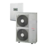
Split air-to-water heat pump with hydrobox
Brand:
Dimplex
| Category:
Heat Pump
| Size: 7.67 MB
Table of Contents
Türkçe
3
Table of Contents
3
1 Lütfen Hemen Okuyun
4
Önemli Notlar
4
Amaca Uygun KullanıM
4
Yasal Yönetmelikler Ve Kurallar
4
2 KullanıM Amacı
5
Uygulama Alanı
5
Genel Özellikler
5
3 Teslimat Kapsamı
5
İç Ünite
5
Kontak Plakası
5
Isı Pompası Kontrol Ünitesi
5
4 Dış Ünite
6
Kurulum
6
Kışın Ve Mevsimlik Rüzgarlarda Dikkat Edilecek Hususlar
8
5 İç Ünite Montajı
8
Genel
8
İç Ünitenin Sabitlenmesi
8
Isıtma Sistemi Bağlantısı
9
6 Devreye Alma
10
Genel
10
Hazırlık
10
Devreye Almada Yöntem Ve Usuller
10
7 Dış Ünitenin Borulu Iletim Ve Kablosunun Bağlanması
11
Soğutucu Akışkan Boruları
11
Elektrik Bağlantıları
13
Son Iş
14
Sızdırmazlık Testi Ve Tahliye
15
8 Kontrol Noktası, BakıM Ve Arıza Giderme
16
Devreye Alma Kontrol Listesi
16
BakıM
17
Arıza Giderme
17
Dış Modül Sıcaklık Sensörü Özellikleri
18
İç Ünite Sıcaklık Sensörü Özellikleri
18
9 Temizlik / BakıM
19
BakıM
19
Isıtma Tarafı TemizliğI
19
10 Arızalar / Sorun Giderme
19
11 Devre Dışı Bırakma / Tasfiye
19
12 Cihaz Bilgisi
20
English
23
1 Please Read Immediately
24
Important Notes
24
Intended Use
24
Legal Regulations and Guidelines
24
2 Purpose
25
Area of Application
25
General Properties
25
3 Scope of Supply
25
Indoor Unit
25
Contact Plate
25
Wärmepumpenmanager
25
4 Outdoor Unit
26
Installation
26
Precautions in Winter and in Seasonal Winds
28
5 Assembly Indoor Unit
28
General
28
Indoor Unit Fixing
28
Heating System Connection
29
6 Commissioning
30
General
30
Preparation
30
Commissioning Procedure
30
7 Connecting the Pipework and Cables to the Outdoor Unit
31
Refrigerant Pipes
31
Electrical Connections
33
Final Work
34
Leak Test and Evacuation
35
8 Test Points, Maintenance and Troubleshooting
36
Checklist Prior to Commissioning
36
Maintenance
36
Troubleshooting
36
Characteristic Curve Temperature Sensor Outdoor Unit
38
Characteristic Curve Temperature Sensor Indoor Unit
38
9 Cleaning / Maintenance
39
Maintenance
39
Cleaning the Heating System
39
10 Faults / Troubleshooting
39
11 Decommissioning / Disposal
39
12 Device Information
40
Operating Limits
40
Polski
43
1 Należy Niezwłocznie Zapoznać Się Z Tekstem
44
Ważne Wskazówki
44
Użycie Zgodne Z Przeznaczeniem
44
Ustawowe Przepisy I Dyrektywy
44
2 Zastosowanie
45
Zakres Zastosowania
45
WłaściwośCI Ogólne
45
3 Zakres Dostawy
45
Jednostka Wewnętrzna
45
Płytka Rozdzielcza
45
Sterownik Pompy Ciepła
45
4 Jednostka Zewnętrzna
46
Instalacja
46
Środki OstrożnośCI Na Okres Zimy Oraz W Przypadku Wiatrów Sezonowych
48
5 Montaż Jednostki Wewnętrznej
48
Informacje Ogólne
48
Mocowanie Jednostki Wewnętrznej
48
Przyłącze Od Strony Grzewczej
49
6 Uruchomienie
50
Informacje Ogólne
50
Przygotowanie
50
Postępowanie Podczas Uruchamiania
50
7 Przyłącza Przewodów Rurowych I Kabli Do Urządzenia Zewnętrznego
51
Rury Czynnika Chłodniczego
51
Przyłącza Elektryczne
53
Prace Wykończeniowe
54
Kontrola SzczelnośCI I Opróżnianie
55
8 Punkty Kontrolne, Konserwacja I Usuwanie Usterek
56
Lista Kontrolna Przed Uruchomieniem
56
Konserwacja
57
Usuwane Usterek
57
Charakterystyki Czujnika Temperatury W Urządzeniu Zewnętrznym
58
Charakterystyki Czujnika Temperatury W Jednostce Wewnętrznej
58
9 Czyszczenie / Pielęgnacja
59
Pielęgnacja
59
Czyszczenie Od Strony Grzewczej
59
10 Usterki / Diagnostyka
59
11 Wyłączenie Z Eksploatacji / Utylizacja
59
12 Informacje O Urządzeniu
60
Unknown
63
Ek / Appendix / Załącznik
63
Boyutlar / Dimension Drawings / Rysunki Wymiarowe
64
Dış Modül Boyutları / Dimension Drawing Outdoor Unit / Rysunek Wymiarowy Urządzenia Zewnętrznego LAK 6IMR-TP / LAK 9IMR-TP
64
Dış Modül Boyutları / Dimension Drawing Outdoor Unit / Rysunek Wymiarowy Urządzenia Zewnętrznego LAK 14ITR-TP
65
Temel Plan / Foundation Plan / Plan Fundamentu
66
İç Modül Boyutları / Dimension Drawing Indoor Unit / Rysunek Wymiarowy Jednostki Wewnętrznej
67
Diyagramlar / Diagrams / Wykresy
68
Eisıtma Çalışma Sınırı / Operating Limits Diagram Heating / Wykres Limitów Pracy, Grzanie
68
Soğutma Çalışma Sınırı / Operating Limits Diagram Cooling / Wykres Limitów Pracy, Chłodzenie
69
AkıM Akış Planları / Circuit Diagrams / Schematy Obwodowe
70
Kontrol / Control / Sterowanie
70
Yük / Load / Obciążenie
71
Bağlantı Planı / Circuit Diagram / Schemat Połączeń
72
Dizin / Legend / Legenda
73
Hidrolik Bağlantı Şeması / Hydraulic Integration Diagrams / Schematy Układów Hydraulicznych
75
Tek Enerjili Sistemleri Bir Isıtma Devresi; Isıtma Ve Dinamik Soğutma / Mono Energy System with One Heating Circuit, Heating and Dynamic Cooling / Instalacja Monoenergetyczna Z Jednym Obiegiem Grzewczym, Ogrzewanie I Dynamiczne Chłodzenie
75
Tek Enerjili Sistemleri Bir Isıtma Devresi; Isıtma Ve Dinamik Soğutma Ve Sıcak Su Hazırlama / Mono Energy
76
Dizin / Legend / Legenda
77
Uygunluk Beyanı / Declaration of Conformity / Deklaracja ZgodnośCI
78
Advertisement
Advertisement
Related Products
Dimplex SIK 14 TE-2
Dimplex LIKI 14TE
Dimplex LA 12S-TUR
Dimplex LA 18S-TUR
Dimplex HPL 18S-TUW
Dimplex LI 16I-TUR
Dimplex 16IHOIAOF6
Dimplex 16CHOIAOF6
Dimplex LIA 1316BWCF
Dimplex HPL 12S-TUW
Dimplex Categories
Indoor Fireplace
Heater
Heat Pump
Stove
Fan
More Dimplex Manuals
Login
Sign In
OR
Sign in with Facebook
Sign in with Google
Upload manual
Upload from disk
Upload from URL