Sign In
Upload
Manuals
Brands
Digital Equipment Manuals
Storage
RK05 Series
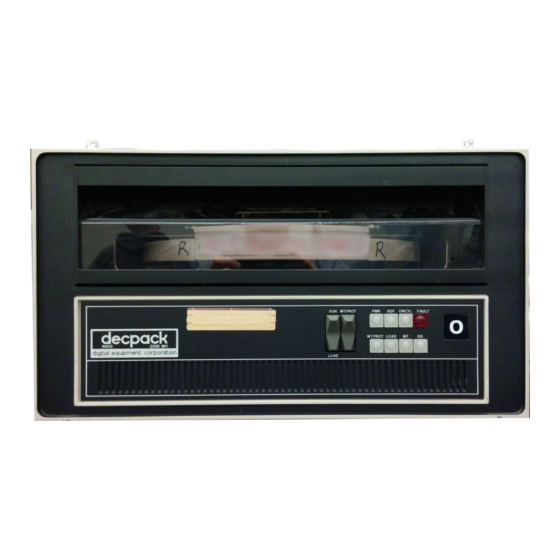
Digital Equipment RK05 Series Disk Drive Manuals
Manuals and User Guides for Digital Equipment RK05 Series Disk Drive. We have
4
Digital Equipment RK05 Series Disk Drive manuals available for free PDF download: Abbreviated Component Maintenance Manual, Maintenance Manual, Workbook
Digital Equipment RK05 Series Abbreviated Component Maintenance Manual (118 pages)
disk drive
Brand:
Digital Equipment
| Category:
Computer Hardware
| Size: 4 MB
Table of Contents
Table of Contents
3
50160 Hz POWER OPTION
8
Controls and Indicators
8
General Information
8
Introduction
8
Major Assemblies and Systems
8
Specifications
8
Warranty
8
Performance Specifications
9
Airsystem
11
Cartridge-Handling System
11
Controlsandindicators
11
Linear Positioner
11
Logic Assembly
11
Power Supply 1
11
Spindle and Drive
11
Installation
18
Unpacking and Inspection
18
Mechanical Installation and Checkout
20
Cartridge Handling Practices and Precautions
23
Cartridge Packing and Shipping
23
Cartridge Loading
24
Cartridge Unloading
24
Normal Operating Procedures
24
Cylinder Address (8 Lines)
25
General
25
Input Interface Lines
25
Interface
25
Rk11-D
25
Select (4 Lines)
25
Strobe
25
Address Accepted
27
File Ready (Drive Ready)
27
Head Select
27
Output Interface Lines
27
Read. Write. or Seek Readyion Cylinder
27
Readgate
27
Restore (RTZ)
27
Write Data and Clock
27
Write Gate
27
Writeprotect Set
27
Aclow 3
28
Dclow
28
Readclock
28
Readdata
28
Sector Address (4 Lines)
28
Sector Pulse
28
Chapter 4 Theory of Operation
29
Stop
29
Track Addressing and Head Positioning
29
Recording Technique
33
Logical Description
33
Start
33
Stop
33
Normal Stop
38
AC LOW Stop
38
DC LOW Stop
38
Disk Drive Addressing
38
Seek
38
Load Heads Seek
38
Forward Seek
40
Reverse Seek
40
Return-To-Zero (Restore) Seek
40
Sector/Index Pulse Generation
40
Carriage Positioning
42
Positioner Servo Description
42
Velocity Mode
42
Detent Mode
42
Servo Circuit Description
43
Linear Positioner Transducer
43
Velocity Function Generator
44
Velocity Synthesizer
44
Readwrite
45
Read Operation
45
Simplified Data Separator Circuit
46
Write Operation
47
Read Waveforms
47
Fault Detection
48
Current Fault
48
Positioner Lamp Fault
48
Chapter 5 Maintenance
50
Recommended Tools and Test Equipment
50
Recommended Tools and Test' Equipment
50
Preventive Maintenance
50
500-Hour PM Procedure
50
Absolute Filter Removal and Replacement
54
Linear Positioner
54
Absolute Filter Removal
54
Internal Power Supply Connections
55
Carriage
56
Carriage Removal
56
Carriage Replacement
57
Carriage Bearing Assembly Removal
57
Carriage Bearing Assembly Replacement
57
Carriage Bearing Assembly Removal
58
Head Removal. with Head Insertion Tool
61
Head Replacement. with Head Insertion Tool
61
Spindle
63
Spindle Replacement
63
Spindle Ground (Carbon Brush) Removal and Replacement
64
Spindle Drive Motor
64
Motor Removal
64
Motor Replacement
64
Spindle Replacement
64
Drive Belt Removal and Replacement
65
Carbon Brush Replacement
65
Blower Motor
66
Blower Removal
66
Blower Replacement
66
Power Supply Removal
66
Cartridge Cleaning
66
Cartridge Cleaning Procedure
66
Adverse Disk Conditions
69
Alignment. Checks. and Adjustments
69
Alignment Cartridges
69
231 5 CE Test Cartridge Shim Installation
70
Servo System Timing Checks and Adjustments
70
Considerable Runout
70
CE Test Cartridge Shim Installation
71
Dynamic Off-Line Checks and Adjustments
72
Servo System Adjustments
74
Cosine Amplitude/Offset Waveform
76
Full Stroke Waveform
77
Full Stroke Position Waveform
77
Static Tests and Adjustments
78
Readprite Head Check and Alignment
79
Index/Sector Timing Adjustment
88
Cartridge-To-Receiver Clearance
92
Cartridge Receiver Clearances
92
Door Locking Bar Location
95
Cartridge Seating Elements
95
Advertisement
Digital Equipment RK05 Series Maintenance Manual (78 pages)
Disk Drive
Brand:
Digital Equipment
| Category:
Storage
| Size: 4 MB
Table of Contents
Table of Contents
4
Chapter 1 General Information
10
Introduction
10
Specifications
10
50/60 Hz Power Option
11
Major Assemblies and Systems
12
Air System
12
Controls and Indicators
13
Spindle and Drive
15
Linear Positioner
16
Cartridge Handling System
16
Electronic Module
18
Air System
18
Power Supply
18
Chapter 2 Inst Allation
19
Unpacking and Inspection
19
Mechanical Installation and Checkout
19
Operation
21
Disk Cartridge Installation and Removal
21
Normal Operating Procedure
21
Chapter 3 Interface
23
General
23
Input Interface Lines
23
Select (4 Lines)
23
Cylinder Address (8 Lines)
23
Strobe
23
Head Select
24
Write Protect Set
25
Write Data and Clock
25
Write Gate
25
Restore (RTZ)
25
Read Gate
25
Output Interface Lines
25
File Ready
25
R/W/S Ready (Read, Write, or Seek Ready)
25
Address Accepted
26
Address Invalid
26
Seek Incomplete
26
Write Protect Status
26
Write Check
26
Read Data
26
Read Clock
26
Sector Address (4 Lines)
26
Sector Pulse
27
Index Pulse
27
Aclow
27
DC Low
27
High Density
27
Chapter 4 Theory of Operation
28
Functional Description
28
Start
28
Stop
28
Track Addressing and Head Positioning
29
Read/Write Heads
31
Stop Flow Chart
31
Read/Write Head
31
Seek Flow Chart
32
Recording Technique
34
Logical Description
34
Power On/Off Sequence
34
Head Loading
34
Start
35
Double Frequency Pulse Relationship
36
Control and Interlock Block Diagram
37
Stop
38
Normal Stop
38
Low Speed Stop
38
AC Low Stop
38
DC Low Stop
39
Disk Drive Addressing
39
Seek
39
Load Heads Seek
39
Forward Seek
40
Reverse Seek
41
Return-To-Zero (Restore) Seek
42
Position Servo Logic
42
Velocity Mode
43
Linear Position Transducer
43
Velocity Synthesizer
44
Velocity Synthesizer Timing
45
Detent Mode
46
Sector/Index Pulse Generation
46
Read Operation
48
Read Timing
49
Write Operation
50
Fault Detection
50
Erase Current Fault
51
Positioner Lamp Fault
51
Power Supply Description
51
Chapter 5 Maintenance
52
Recommended Tools and Test Equipment
52
Preventive Maintenance
52
Elapsed Time Indicator
53
500-Hour PM Procedure
54
Prefilter Removal
54
Prefilter Removal and Replacement
55
Absolute Filter Removal and Replacement
55
Corrective Maintenance
56
Linear Positioner
56
Ll Positioner Removal
56
Positioner Replacement
56
Absolute Filter Removal
56
Carriage
58
Carriage Removal
58
Carriage Replacement
58
Carriage Removal
59
Carriage Bearing Assembly Removal
60
Carriage Bearing Assembly Replacement
60
Transducer Block Removal and Replacement
60
Carriage Bearing Assembly Removal
61
Servo System Timing Adjustment
62
64-Cylinder Seek Waveform
64
Read/Write Heads
65
Head Removal
65
Head Replacement
65
Read/Write Head Alignment
66
Read/Write Head Adjustments
66
Read/Write Data Separator (G 180 Card) Adjustment
67
Read/Write Head Alignment Waveforms
68
Spindle
69
Spindle Removal
69
Spindle Replacement
69
Spindle Replacement
70
Spindle Drive Motor
71
Motor Removal
71
Motor Replacement
71
Drive Belt Removal and Replacement
71
Blower Removal
72
Blower Motor
73
Blower Replacement
73
Spare Parts List
74
Troubleshooting
75
Digital Equipment RK05 Series Maintenance Manual (113 pages)
Brand:
Digital Equipment
| Category:
Computer Hardware
| Size: 2 MB
Table of Contents
Table of Contents
5
Bus Terminator Module
11
Exerciser Chassis
11
General Description
11
General Information
11
Introduction
11
Physical Description
11
Front Panel
12
Positioner Exerciser Module
12
Writer Exerciser Module
12
Power Cable
13
Set-Up Procedure
13
Unpacking Procedure
13
Acceptance Test Procedure
15
Writer Exerciser Module Test Procedure
15
Positioner Exerciser Module Test Procedure
18
Chapter 3 Operation
21
Scope
21
Controls and Indicators
21
Modes of Operation
23
Stepmode
23
Alternate Mode
23
Oscillate Mode
23
Random Mode
24
Utilization Procedure
24
Theory of Operation
29
Scope
29
Functional Description
29
Clock and Data Output Multiplexer
29
Fault Detect Logic
29
Writer Exerciser
29
Write Control Logic
29
Positioner Exerciser
29
Strobe Oscillator
30
Address Counter Control Logic
30
Address Counter
30
Cylinder Address Source Select Logic
30
Flow Diagram Description
39
Maintenance
45
Scope
45
Maintenance Philosophy
45
Test Equipment Required
45
Preventive Maintenance
45
Corrective Maintenance
46
Rk05 Disk Drive Maintenance Using the Rk05 Exerciser
49
Scope
49
Alignment. Checks. and Adjustments
49
Alignment Cartridges
49
RK05K-AC Alignment Cartridge
49
Servo System Timing Checks and Adjustments
50
Dynamic Off-Line Checks and Adjustments
52
Static Tests and Adjustments
57
Readiwrite Data Separator (G180 Card) Adjustment
58
Readwrite Head Check and Alignment
58
RK05K-AC Alignment Cartridge
59
Index/Sector Timing Adjustment
65
RK05K-AC Alignment Cartridge
65
Cartridge Receiver Alignment
68
7442 4-Line-To-10-Line Decoders
72
7474 Dual D-Type Edge-Triggered Flip-Flops
72
23 Monostable Multivibrator
72
74193 Synchronous 4-Bit Upidown Counter (Dual Clock with Clear) a
75
Advertisement
Digital Equipment RK05 Series Workbook (66 pages)
Subsystem Maintenance SPI Course, Laboratory Projects Workbook
Brand:
Digital Equipment
| Category:
Laboratory Equipment
| Size: 2 MB
Table of Contents
Table of Contents
5
Carbon Brush Replacement
11
Blower Motor Removal
12
Full Stroke Profile Waveform
15
Negligible Runout
19
Considerable Runout
20
RK05K-AC Head Alignment Waveform
21
Index/Sector Waveform
24
A-I
27
Volt Regulator
27
C4 Waveform
28
Gain Waveform
29
Sine Amplitude/Offset and Velocity Offset Waveform
41
Cosine Amplitude/Offset Waveform
42
Velocity Amplitude Waveform
42
Acceleration Waveform
44
Full Stroke Position Waveform
45
Outer Limit Waveform
46
E-L
48
Location of Scale Retaining Screws
50
How to Read a Vernier
51
RK05K-AC Head Alignment Waveform
53
Read/Write Head Adjustments
56
F-L
59
How to Read a Vernier
60
Index/Sector Waveform
62
Advertisement
Related Products
Digital Equipment RK06
Digital Equipment RK07
Digital Equipment RK05AA
Digital Equipment RK05AB
Digital Equipment RK05BA
Digital Equipment RK05BB
Digital Equipment RA70
Digital Equipment RA73
Digital Equipment RA71
Digital Equipment RL01
Digital Equipment Categories
Desktop
Server
Computer Hardware
Printer
Storage
More Digital Equipment Manuals
Login
Sign In
OR
Sign in with Facebook
Sign in with Google
Upload manual
Upload from disk
Upload from URL