Sign In
Upload
Manuals
Brands
Diatron Manuals
Laboratory Equipment
Abacus 5
Diatron Abacus 5 Manuals
Manuals and User Guides for Diatron Abacus 5. We have
1
Diatron Abacus 5 manual available for free PDF download: Operator's Manual
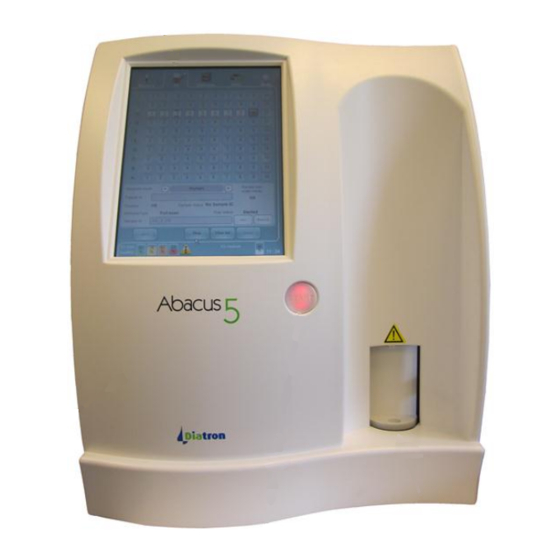
Diatron Abacus 5 Operator's Manual (165 pages)
Brand:
Diatron
| Category:
Laboratory Equipment
| Size: 7 MB
Table of Contents
Table of Contents
8
1 Indications for Use
18
2 For Your Safety
18
Who Should Use this Manual
18
Special Symbols Used in this Manual
18
General Precautions
18
Environmental Factors
20
Electrical Requirements
20
Space Requirements
20
Figure 1. Abacus 5 with Autosampler Space Requirements
21
Weight Requirements
22
Figure 2. Abacus 5 Without Autosampler Space Requirements
22
Waste Disposal
23
Known Limitations
23
Emergency Situations
23
3 Product Support
24
4 Installation
26
The 'Abacus 5' Analyzer Package Contents
26
The Autosampler Package Contenta
26
5 General Overview and Principles of Operation
28
General Overview
28
Measured Parameters
28
Approved Reagents and Control Materials
29
Table 1. 'Abacus 5' Analyzer Parameters
29
Genuine Diatron Reagents
30
Table 2. Diatro•Dil-5P Diluent Information
30
Table 3. Diatro•Lyse-5P Information
30
Table 4. Diatro•Diff-5P Information
31
Table 5. Diatro•Hypocleaner CC Information
31
Principles of Operation
32
Volumetric Impedance Method
32
Photometric Light Absorbance Method
32
Figure 3. Volumetric Impedance Method
32
Optical Light Scatter and Diffraction Method
33
Figure 4. Photometric Light Absorbance Method
33
Figure 5. 'Abacus 5' Optical Head Block Diagram
33
Figure 6. Optical Signal Processing System
34
Figure 7. Cellular Light Scatter
34
Inside the 'Abacus 5' Analyzer
35
Front Panel
35
Figure 8. 4DIFF Scatter Diagram
35
Figure 9. Abacus 5 Front Panel
35
Back Panel
36
Figure 10. Abacus 5 Back Panel
36
Figure 11. Main Board Back Panel I/O Ports
37
Table 6. Reagent Connector Color Codes
37
Left Side Assembly
38
Figure 12. Left Side Assembly
38
Right Side Assembly
39
Figure 13. Left Side Assembly
39
Front Assembly
40
Figure 14. Front Assembly Behind the Front Panel
40
6 User Interface
42
Using the Touch Screen
42
Using the 'Start' Button
42
Using an External Mouse
42
Using an External Keyboard
42
Using the On-Screen Virtual Keypads
43
Figure 15. Alphanumeric Virtual On-Screen Keypad
43
Figure 16. 'Sticky' Shift and Symbol Buttons
43
Using the Graphical User Interface
44
Figure 17. Numeric Virtual On-Screen Keypad
44
Figure 18. Date Virtual On-Screen Keypad
44
Figure 19. Graphical User Interface Sections
45
Quick Links
45
The Interactive Display Area
45
The Status Display
45
Entering Information
46
The Menu System
46
Primary Menu Items
46
Starting a Manual Single Tube Measurement
46
Figure 20. the Status Display
46
Start Automated Measurements
47
Access the Database
47
Initiate Printing
47
Main Menu
47
Autosampler Control Panel
48
Adjust the Time and Date
48
Open the Warning Panel
48
Menu Tree
48
Figure 21. 'Abacus 5' Main Menu
48
Safety Access Codes
51
Table 7. 'Abacus 5' Analyzer Menu Tree
51
7 Start up and Shut down the 'Abacus 5
52
Start up and Shut down Overview
52
Starting up the 'Abacus 5' Analyzer
52
Visual Inspection
52
Power up the 'Abacus 5' Analyzer
52
Start up the User Interface
53
Figure 22. 'Abacus 5' Analyzer Startup and Log on Screens
53
User Logon
54
Pneumatic System Start and Blank Measurement
54
Exiting the 'Abacus 5' Analyzer
55
Log off
55
Figure 23. Abacus 5 Shutdown Options
55
Figure 24. Log off
55
Shut down
56
Prepare for Shipment
56
Figure 25. Shut down
56
Figure 26. Prepare for Shipment
56
Figure 27. Connect Distilled Water Panel
57
Emergency Shut down
58
Figure 28. Remove Reagent Tubing Panel
58
Figure 29. Shut down Ready Panel
58
Repackaging the 'Abacus 5' Analyzer
59
8 Sample Measurement
60
Sample Types Supported by the 'Abacus 5
60
Supported Sample Tubes Types
60
Sampling Depth
60
Open or Closed Sample Tubes
61
Sample Collection and Handling
61
Figure 30. Sampling Needle
61
Sample Types and Modes
62
Sample Identification
62
Running Samples
63
Manual Mode
63
Figure 31. Sample Measurement Panel
64
Automatic Mode
65
Figure 32. Sample Processing Result Screen
65
Figure 33. Autosampler Info and as Panel
66
Table 8. Supported Autosampler Bar Code Reader Symbologies
67
Figure 34. Full Scan Automatic Processing Mode
68
Figure 35. Full Scan Mode Tray View Progress
69
Figure 36. Full Scan Mode Tray and List Views
70
Figure 37. Free List Mode Selection
71
Figure 38 Figure 39. Preparing a Free List
72
Figure 40. Free List Mode Progress: List View
72
Figure 41. Free List Mode Progress: Tray View
73
Figure 42. Selected Sample Mode Panel
74
Result Display
75
Figure 43. Control the Autosampler with Info Panel
75
Printing Reports
76
The Measurement Process
76
Figure 44. Results Display and Magnified Scatter Plot
76
Figure 45. 'Abacus 5' Measurement Process
77
9 Result Interpretation
78
The Result Screen
78
Sample Identification Information
78
Figure 46. 'Abacus 5' Result Screen
78
Parameter Information
79
Figure 47. Parameter Information Display
79
Table 9. Sample Identification Information
79
Figure 48. Graphical Normal Range Display
80
Scatter Diagrams and Histograms
80
Table 10. Normal Range Flags
80
Table 11. Linearity Range Flag
80
Table 12. High Blank Flag
80
Figure 49. Result Screen Scatter Diagrams
81
Figure 50. Result Screen Histograms
81
Figure 51. Warnings Section of Results Screen
82
Warnings
82
Table 13. Warning Flags
86
Table 14. Interpretive Flags
87
Table 15. Morphological Flags
87
10 Database Functions
88
Database Overview
88
Figure 52. Accessing the Database
88
Scrolling the Database View
89
Sorting Database Information
89
Figure 53. Scrolling and Selecting
89
Table 16. Database Sort Criteria
89
Manual Selection of Database Records
90
Automatic Selection of Database Records
90
Viewing Detailed Results
90
Figure 54. Multiselect and Multiple Selection
90
Statistics
91
Managing Database Records
91
Select by
91
Figure 55. Manage Records Panel
91
Figure 56. Select by Panel
91
Importing
92
Figure 57. Database Importing Panel
92
Export
93
Send to LIS
93
Save Tab File
93
Figure 58. Directory Panel for Data Storage
93
Save Raw Data
94
Delete
94
11 Calibration
96
Calibrating the 'Abacus 5
96
Figure 59. Calibration Options
96
Figure 60. Calibration Panel and Calibration Run Result Panel
97
Figure 61. Calibration Factor Panel
98
View Calibrations
98
Figure 62. View Calibration Panel
99
12 Quality Control
100
Set QC Reference
100
Figure 63. QC Panel
100
Figure 64. Set QC Reference Panel
101
Figure 65. Load QC Reference Panel
101
QC Measure
102
View QC References
102
View QC Data
102
View QC Diagrams
102
View X-B Data
102
Figure 66. View QC Diagrams Panel
102
View X-B Diagrams
103
13 Patients
104
Figure 67. Patients Panel
104
Figure 68. Edit Patient Panel
105
14 Multi-User Mode
106
Types of Users
106
Creating a New User
106
Table 17. Restrictions by User Type
106
Figure 69. Logon Panel
107
Figure 70. Add User Panel
107
Figure 71. Add User Complete Panel
107
Deleting or Changing Users
108
Figure 72. Settings Panel (Administrator User)
108
Figure 73. Settings Panel (Administrator User)
109
Figure 74. Confirm User Delete Panel
109
15 Settings
110
Customize Settings
110
Figure 75. Settings Panel
110
Laboratory Settings
111
External Devices
111
Figure 76. Customize Settings Panel
111
System Settings
112
Figure 77. External Devices Settings Panel
112
Figure 78. System Settings Panel
113
Units
114
Printer Settings
114
Figure 79. Units Settings Panel
114
Table 18. Count Unit Parameters
114
Profile Limits Settings
115
Figure 80. Printer Settings Panel
115
X-B Settings
116
Figure 81. Profile Limits Settings Panel
116
User Settings
117
Date and Time Adjustment
117
Figure 82. X-B Settings Panel
117
Figure 83. User Settings Panel
117
Figure 84. Time/Date Settings
118
16 Instrument Diagnostics
120
Analyzer Self Test
120
Figure 85. Diagnostics Panel
120
Figure 86. Self Test Panel
121
Log
122
Figure 87. Log Panel
122
Table 19. Self Test Item Limits
122
Reagent Status
123
Figure 88. Reagent Status Panel
123
Table 20. Log Filters
123
Statistics
124
Information
124
Figure 89. Statistics Panel
124
Figure 90. Information Panel
125
17 Maintenance
126
Opening the Front Panel
126
Closing the Front Panel
126
Figure 91. Opening the Front Panel
126
Removing the Side Panels
127
User Maintainable Parts of the Analyzer
127
Figure 92. Closing the Front Panel
127
Software Maintenance Functions
128
Figure 93. Software Maintenance Functions
128
Cleaning the Shear Valve
129
Table 21. Software Maintenance Procedures
129
Figure 94. Shearvalve Cleaning Maintenance Function
130
Figure 95. Shearvalve Cleaning Maintenance Function Prompt
130
Figure 96. Removing the Shear Valve Axis Thumbscrew
131
Figure 97. Disassembling the Shear Valve
131
Cleaning the Washing Head
132
Figure 98. Cleaning the Shear Valve
132
Figure 99. Reassembling the Shear Valve
132
Software Cleaning Maintenance Functions
133
Figure 100. Removing the Washing Head
133
Figure 101. Cleaning the Washing Head
133
Cleaning the Measurement System
134
Daily Cleaning
134
Extended Cleaning (Hard Cleaning)
134
Replacing Reagents
135
Figure 102. Reagent Low Indicator and Explanation Panel
135
Figure 103. Reagent Replacement Panel
136
18 Reagent Locking
138
Figure 104. Location of Reagent Key in Diatro•Lyse-5P Reagent Container
138
Figure 105. Reagent Key Connector
138
19 The Daily Routine
139
20 Troubleshooting
142
Software Error Messages
142
Pneumatic Error Messages
142
Figure 106. Pneumatical Error Message Example
142
Mechanical Problems
143
Sample Rotor (SR) Failures
143
Needle Mechanics, Vertical Motor (Mvert) Problems
143
Figure 107. Detailed Error Message
143
Shear Valve (SV) Related Errors
144
Dilutor Errors
144
Figure 108. Proper Seating of Shear Valve Thumbscrew
144
Priming Problems
145
Electronics Related Problems
145
The Analyzer Does Not Power on
145
I 2 C Errors Displayed at Startup
145
Measurement Results Related Problems
145
Fluctuating PLT Background Values
145
Long, Smeared Population
146
Figure 109. Smeared Population
146
22 Appendix
148
Reagent Consumption
148
Table 22. Reagent Consumption
148
Display Ranges
149
Table 23. Display Ranges
149
Fluidic System
150
Figure 110. Fluidic System Diagram
150
Printed Report Formats
151
Figure 111. Detailed Printout Format
151
Figure 112. Listed Printout Format
152
Parameter Calculation
153
Table 24. Parameter Calculation
154
Specifications
155
Table 25. Specifications
156
Performance Characteristics
157
Precision
157
Accuracy
157
Linearity
157
Table 26. Precision Performance
157
Table 27. Accuracy Performance
157
Table 28. Linearity Performance
157
Carryover
158
Sample Stability
158
Mode to Mode
158
Reference Ranges
158
Table 29. Carryover Performance
158
Table 30. Closed Vs. Open Vial Mode Performance
158
Table 31. Closed Vs. Autosampler Mode Performance
158
Background Limits
159
Analytical Measurement Range
159
Table 32. Reference Ranges
159
Table 33. Background Limits
159
Interfering Substances
160
Table 34. Analytical Measuring Range
160
Reagent System
161
Diluent
161
Lyse Reagent 1
161
Lyse Reagent 2
161
Cleaner
161
Tab File Format
162
21 Accessories
148
23 Index
163
Advertisement
Advertisement
Related Products
Diatron Abacus Junior Vet
Diatron Abacus junior 30ND
Diatron Abacus junior 30
Diatron Abacus junior 5
Diatron ABACUS 4
Diatron Abacus +
Diatron Categories
Measuring Instruments
Laboratory Equipment
Medical Equipment
More Diatron Manuals
Login
Sign In
OR
Sign in with Facebook
Sign in with Google
Upload manual
Upload from disk
Upload from URL